Other coverage of horizontal windmills:
| location | |
| state | |
| date | |
| builder | |
| designer | |
| condition | |
| purpose |
| location | |
| name | |
| state | |
| date | |
| designer | |
| purpose |
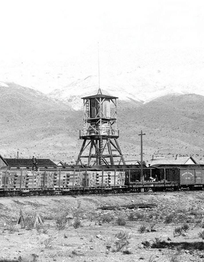
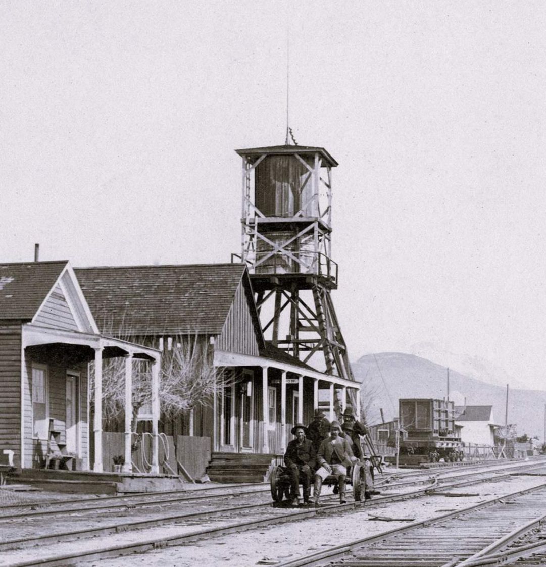
For a railroad use, Southwick consistently advertised that his windmill+tank would be perfect for railroads, and even illustrated it in that use. ... The only instance I've seen of a railroad buying this windmill is just south of Philadelphia, in Paschalville, on the short-lived Philadelphia, Wilmington and Baltimore RR. Only a library seems to bear the name of Paschalville, since all appears to be absorbed into Philly suburbia.
| location | |
| state | |
| date | |
| purpose | |
| sails |
To Thomas Gilpin
London March 18. 1770
...
I have seen but two horizontal Windmills in all my Travels. The first was at Rhode island, where the Sails were in the Form of the Foresail and Mainsail of a Sloop, four little Masts with such Sails were fix'd upright on the four Ends of a horizontal Cross; the Sails fill'd and jib'd successively as the Cross went round: It was over a Turner's Work Shop and the Application was to drive a large Lathe for turning heavy Mortars of Lignum Vitae.
| location | |
| state | |
| name | |
| designer | |
| builder | |
| date | |
| sails | |
| purpose |
To Thomas Gilpin
London March 18. 1770
...
I suppose you may not have had an Opportunity of knowing that the Manner of fixing your Sails, tho truly invented by you, has before been thought of by others. I did myself about 25 years ago make a little Model for W. Masters who had thoughts of executing it in large for Use. It was in all respects the same, except the Cord and Spring to each Sail which are in yours, and which I think may be a great Improvement; and except that I plac'd my Sails upright on their Ends; which I mention now for your Consideration whether the Force or Purchase is not thereby greater, no Part of it being so near the Center of Motion as when they lie on their Sides, and fall inwards; but of this I would not be positive. In a second Model I plac'd six Sails instead of four, for which there is good room when so plac'd upright, and I thought the Motion might thereby be more equable. A Friend of mine in Maryland, Mr. H Jones, to whom I had communicated this horizontal Windmill wrote a Paper about it which he printed, and with some Alterations erected a large one on his Land intending to apply it to the grinding of Corn; he nam'd it the Elephant from its suppos'd Strength: and when used in a Current of Water, which he also propos'd, would then have it call'd the Whale; but before his Elephant was finish'd a great Storm shatter'd it to Pieces, and he never repair'd it.
| location | |
| state | |
| name | |
| owner | |
| date | |
| note |
| location | |
| state | |
| name | |
| date | |
| designer | |
| purpose |
| location | |
| state | |
| name | |
| date | |
| designer |
Dr. Bruff, the city's earliest practising dentist, being something of an inventor as well, built on Observatory Hill a lofty wooden tower from whose top he demonstrated his favorite "horizontal windmill."Letter to Thomas Jefferson from Thomas Bruff, 21 March 1808
Sir.Letter to Thomas Jefferson from Thomas Bruff, 14 September 1808
I am persuaded that any attempt to call your attention, at this interesting period of our publick affairs, to any thing I could produce, needs an apology and the only one I am able to offer, arises out of the present situation of the country, and the necessity there will shortly be of exerting mechanical talents, which I hope will yet find encouragement in a land so favourable to thier compleat success.
Since I took the liberty of addressing you on a former occasion, I have produced, besids some smaller maters, two things which I think of some moment to the public, a new fire engine, intirely different from any thing I have seen or heard of; and a permanent horizontal wind mill, capable of moving machinery of any burden.
I have witness'd the deficiency of engines in several instances, ob[...] with astonishment—what labour was applied, and to what little pu[...]. At that time I had never seen or had a description of thier inside works, but adjusted a plan in my mind, of such a machine as I supposed ought to be used, and if used, could not imagine how such labour could be necessary. After commiting the outlines of my plan to paper, I got an opportunity of examining one in this city, and to my surprize, found not only the principle entirely different from mine, but many more obstructions than I could have had an idea of. I look'd at it with amazement, and could not imagine how it was, that in so old an invention the defects had never been discover'd. I then examined the Enciclopedia, but finding nothing in the cuts like mine, determined further to consider and mature my plan, till some fortunate circumstance, (if such ever occur'd.) should enable me to execute it to my mind. The lever of the smallest I have seen, measures 40 inches from the pevet on which it turns, to the extremity; in such an one, I gain 9 inches, in the application of force, which is 2/9ths of the whole, an advantage I think worthy of attention, but I have others that are more than equal to it Viz. applying the force in a right direction, removing obstructions to the course of the stream, condensing the water gradually, and preventing the danger of choaking.
I have made a windmill in miniature, on my plan, 21 inches diameter, which when placed in the wind, goes so fast the sails could scarcely be seen, if they were not white. They are defended from the weather; there is no counteraction from the wind, as it can only act where it is wanted. It recieves the blast as well from one quarter as another, the force can be increased or diminish'd to almost any degree, and is so perfectly manageable without reefing, as to accommodate it in a few seconds to the rising and falling of the wind in variable weather. Being moved by the application of two levers or arms at the same time, its motion is so uniform and steady, as to fit it, in the opinion of the best judges, for the manufactory of flour, sawing timber of any size, or for working machinery of any kind. Ten or twelve feet squair of canvass spread full to the wind, like the taut sail of a vessel, will give great force; and that force may be increased by enlarging the sails or lengthening thier levers, as my calculation is only made to 24 feet diameter. I should take much pleasure in laying my plans before you, if an opportunity should present itself that would make it agreable to you.
I am verry respectfully Your Hl. Servt.
Thos. Bruff
Washington City Septr. 14th 1808.Letter from Thomas Jefferson to Thomas Bruff, 7 June 1812
Sir.
It is with reluctance I trouble you with my trifling affairs, but a sense of duty impells me on the present occasion. In consequence of your kind offer when I shew'd you the drawing of my horizontal windmill, to make an exception in its favour, in the law respecting wooden buildings, I determined in my mind to make an effort to build it, and with the advice of some of my neighbours, drew up a subscription, to raise the sum of one thousand dollars in shares of [$]50 each, to purchase ground and build a mill to manufacture corn meal in the city. The subscription is nearly filld, at least 17 out of the 20 are taken, and the workmen ready to contract, but I could not be satisfy'd to begin the building, without informing you of it. I saw so little prospect of success when I shewd you the drawing, that, tho I felt the obligation your offer laid me under, I thought it might give you unnecessary trouble, therefore said but little about it, but my business being almost totally suspended, I am glad to find any thing to assist me in the support of a growing family, and the half of the little mill which I am to hold as inventor, will be of some consequence to me in that respect. Doctor Tucker, who is the largest subscriber, advised me to write, that if there was any objection, a notice from you might determine the business: While I am writing I beg leave to draw your attention to another subject, which I hope will meet your approbation; I have found the means of making patent shot by pressure, and in a rapid manner. I tried it on a piece for a bullet of the ounce size, which it made compleatly, and consolidates the metal so compleatly, that it contains the weight of a large duck shot more than an ounce. The shot have been examined by a number of persons, merchants and others, are pronounced verry compleat, and judging by their weight, perfect roundness, and polishd surface, they cannot be excelld. I really wish I had opportunity of sending you samples, as I know your desire to promote home manufactories. I could make bullets in any quantity, for the army and navy, cheaper than they can be cast, and there would be no hollow and whistling ones among them. The following statement, which may be rely'd on as proved, to a certainty, will shew something of the profit attending such an establishment.
[Apologies for the poorly formatted table that follows here - I have been unable to access an image of the original, and the transcription is not good at this point, but I have done my best to arrange it to make sense]A Wheel to be turnd by wind, only 3 feet diameter, the circumference of which is 9 Feet on the axil of the windmill. Having 4 falls to the foot to work the cutters 4 -- 36 The cutters take out in a minute 15 shot 15 27 of which weigh an ounce -- 540 I could work 8 of the machines or cutters but say 4 -- 2160 The model of the windmill, makes from 100 to 140 revolutions in a minute, but I will say 5 when burdend with machinery. -- 10800 Minutes [in an hour] 60 -- 648000 Hours in a day 8 -- Shot in an ounce 27/ 5184000 Ounces in a pound 16/ 192000 Product 12000 lb in 8 hoursShot sells at 13 to 14 & ½ Dollars per hundred, and lead at 9 Dollars. I am offerd 300 ton per year to work up at a third for working beside the applications in the district and from Baltimore. I can make the machinery, and believe I could compleat the establishment for 3000 Dollars, if I can find a friend for that sum, and am confident the institution will repay him in less than a year, but I am far seperated from my friends, and fear I shall not be able to get a name for the bank. My judgment always approved of the embargo, tho I knew it would injure my business, but if it were taken off tomorrow, my affairs would not be mended by the capture of our ships. Therefore as one business is suspended, I am compelld to seek another, and if I can succeed in establishing the shot business to one twentieth the present calculation, it will support my family, and place me in independent circumstances. With my best wishes for your health and happiness, I remain Sir Your huml. Servt.
Thos. Bruff
Monticello June 7. [18]12.Thomas Bruff was known as a dentist and inventor, responsible for six patents. He moved to Washington in 1802, and died in 1816. Bruff didn't apply for a patent on his windmill, but did get Patent 198X for a hand operated coffee mill.
To Thomas Bruff
Sir
I have duly recieved your letter of May 30. and am very happy to learn that your manufactory of solid shot is likely to get into operation; while their quality will command a preference in the private demand, there can be no doubt but the same circumstance will ensure you the public supply. having other occasion to write to the president I have with pleasure added a recommendation of yourself and your manufactory to his attention. wishing you all possible success, I tender you the assurance of my esteem & respect.
Th: Jefferson
The National Tribune, January 27, 1898
Historic Homes of Washington
Noted men and women who have inhabited them.
By Mark S. Lockwood.
...
As Observatory Hill has undergone many changes in title, it may be interesting to the reader to note some of the many legends that gave rise to its different names, ...
Dr. Bruff, the first pratitioner of dentistry in the Federal metropolis, in the year 1810, built upon the southwest side, near the River, a lofty wooden tower, upon the top of which he placed a windmill, which he had invented and patented, calling it "horizontal windmill."
Thus the hill adjoining was known as "Windmill Hill" until the year 1814, when the District militia had a practice and drill camp there, under the command of Col. Thomas L. McKenny, which changed the name to "Camp Hill". This continued to be its name until it was christened Observatory Hill.
| location | |
| state | |
| date | |
| designer | |
| purpose | |
| note |
Boston June 20. 1795.
From Henry Knox
Dear Sir
I received your kind favor of the 1st. instant two days ago. Mr. Joseph Pope of this Town the inventor of the improvements in the horizontal Mills, and the proprietor of the Patent has lately still further improved them, so as to carry four pairs of stones. He is my particular acquaintance, and he will immediately have accurate drawings made and transmitted to you by which, with the descriptions, you will be enabled without further difficulty to erect one by your own workmen. Those which have been erected here answer well for small work. ...
H Knox
| location | |
| name | |
| state | |
| date | |
| purpose | |
| millid | us87 |
| location | |
| name | |
| state | |
| date | |
| purpose | |
| millid | us89 |
| location | |
| state | |
| date | |
| purpose | |
| millid | us88 |
| location | |
| name | |
| state | |
| date | |
| purpose | |
| millid | us86 |
| location | |
| name | |
| state | |
| date | |
| millid | us92 |
| location | |
| state | |
| date | |
| purpose | |
| millid | us93 |
| location | |
| state | |
| date | |
| designer | |
| owner | |
| purpose | |
| building |
| location | |
| state | |
| date | |
| owner | |
| purpose |
PRIVATE SALE,The Portland gazette (Portland, Me.), July 14, 1818
At B. C. Attwood's Office, Head of Exchange-Street,
4 cases straw BONNETS
1 pipe Naples BRANDY
2 second hand CHAISE and HARNESS
3O bushels white BEANES
1 Case Letter PAPER
3 do Foolscap do
12 casks Connecticut FLASKS
30 bags double boded SUGAR, of superior quality. for families use
All which will be sold very cheap for Cash or approved Notes
ALSO — 9 shares in the Horizontal WIND-MILL, which is now in complete operation, and manufactures excellent Meal. June 30
New Invention. — Mr. Rufus Porter, of this town, has just completed and got into successful operation, a newly constructed Wind-Mill, differing from all others heretofore used, insomuch that a change of wind does not in the least impede its force or affect the machinery. Its motion is horizontal and is so constructed, that, by the aid of haulyerds inside the mill, she is perfectly manageable by a child 12 years of age. We do not feel ourselves qualified to describe all its peculiarities and excellencies, as we are unacquainted with the general principles of mills — perhaps we may here after undertake it — suffice it at present to say that Mr. Johnson, the experienced miller, who tends it, as well as other good judges declare that it exceeds their most sanguine expectations. We congratulate the citizens of this town upon the facility which is thus afforded of converting grain into meal without the expense and trouble of sending it out of town. — We make no doubt but our merchants, ever ready to reward enterprize and assiduity, will give the mill a trial, and on finding it to answer the recommendations thus given, will bestow on the proprietors that patronage to which they are entitled.Nine months later, the mill was up for sale, the pieces being sold as separate lots, which suggests that the mill may have been damaged and destroyed. The Portland gazette (Portland, Me.), April 27, 1819
We understand Mr. P contemplates adding an other run of Stones, end a Bolt for converting the meal into flour — With regard to the facility of grinding, we will only add, that during a pleasant breeze on Saturday last, she turned out the meal at the rate of a bushel in four minutes.
Will be sold at Auction, without reserve, an SATURDAY next, on the premises, near Green Street, at 11 o'clock —
The Horizontal Windmill,
In lots to accommodate purchasers, viz. the Iron Work - Sails - Rigging - Millstones & the Building.
ATTWOOD & GALVIN, Auct[ionee]rs.
Portland, April 23.
| location | |
| state | |
| date | |
| building | |
| sails | |
| purpose | |
| designer | |
| note |
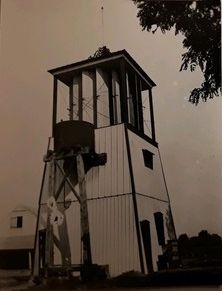
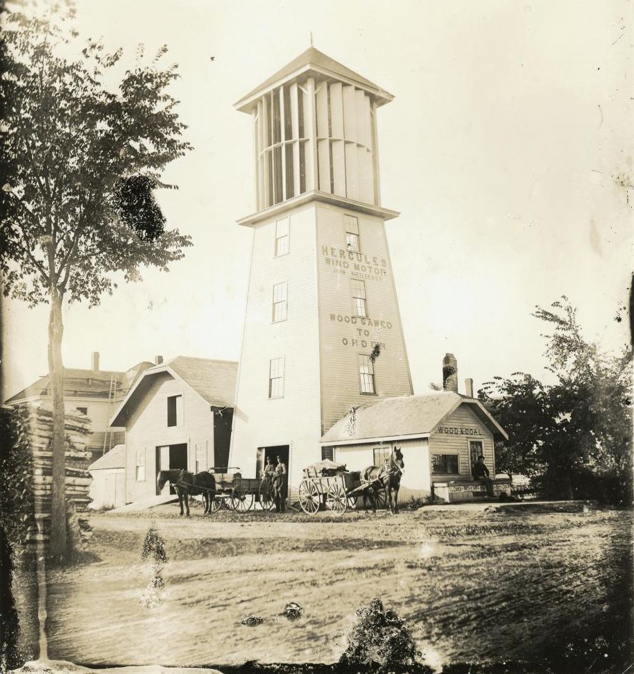
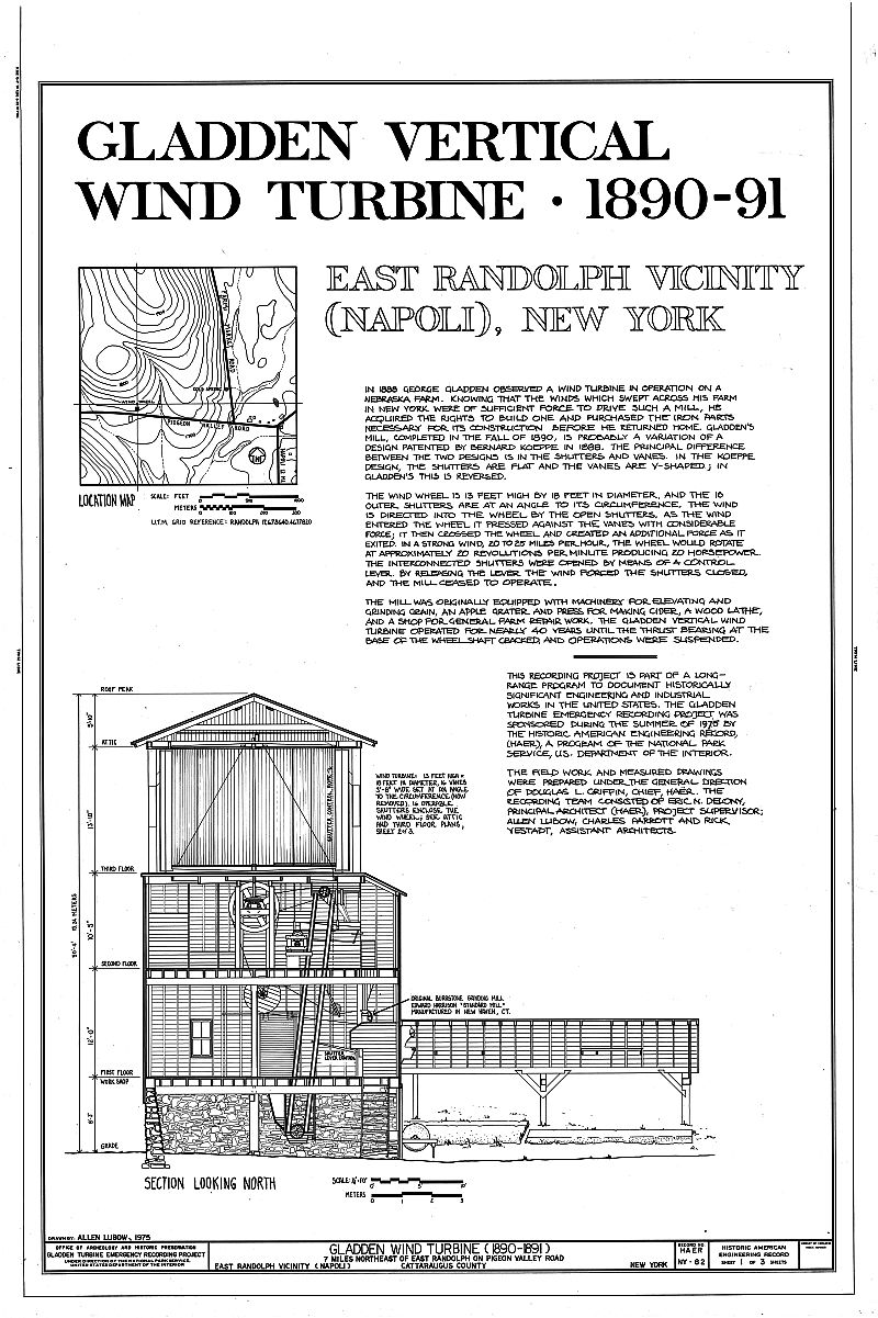
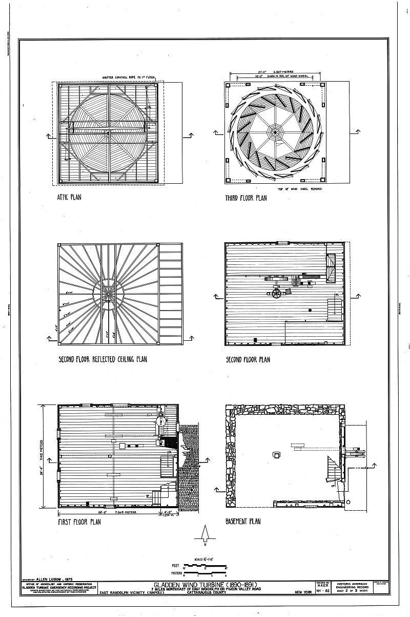
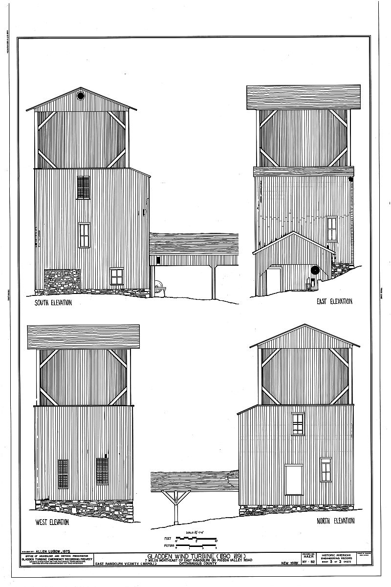
DESCRIPTIONGallery of technical drawingsThe Gladden Milks vertical windmill is a four story wood frame structure built on a stone foundation, with the three lower stories housing the machinery of the mill while a fourth story contains the revolving windwheel. The square portion of the structure below the windwheel has a four foot easterly extension which provides additional storage space. A rectangular one story porch extends from this addition. Both the porch and the windwheel are covered by gable roofs. Board siding with asphalt shingles, in part, covers the exterior walls.
Forming the basis of the interlocking wood frame structural system are "the sills which rest on the masonry walls, the central beam and the center post all of which are hand-hewed beech timbers about 16 inches square .- At the building's corners they are fitted and bolted one over the other so that the 12 inch floor joists would rest on the north and south sills and be flush with the top of the east and west sills.
The technical information in this statement is quoted from Charles Gladden, "Unique Windmill Erected in 1890's Still Stands," Randolph Register, Volume 99, Number 15, July 4, 1958.
STATEMENT OF SIGNIFICANCE"The corner posts, which support:the roof and surround the wind wheel are set at the corners of a 24 foot square. They are hemlock timbers 3 inches square, approximately 88 feet long and extend from the sills below the first floor to the plates supporting the rafters of the roof over the wind wheel. The roof under the wind mill which supports the shutters is constructed with rafters which are arranged radially from the wind wheel shaft so located that each rafter supports one of the shutters directly above it. There is also a distinct pitch of this roof downward in all directions from the center to the outside walls. It is covered by heavy tin sheets interlocked and securely nailed in place, with all joints soldered.
"The wind wheel is 11 feet high by 19 feet in diameter and had 16 interior vanes three feet 8 inches wide which were at an angle to the circumference. These have been removed and used as barn siding nearby. The lower arms of the wheel are covered around the circumference with a wooden platform to which the lower ends of the vanes were attached. The upper end of the wheel is completely covered on the underside of the arms with matched lumber to which the upper ends of the vanes were attached. To insure vertical rigidity of the wheel, 1/2 inch steel rods tie the outer ends of the lower wind wheel arms to the inner ends of the upper arms.
"The 16 shutters surrounding the wheel are of 1-1/4 inch selected matched white pine with an angle at the center of about 157-1/2 degrees so that when closed the outer surface of one shutter will be exactly in line, or in the same plane, with the inner surface of the next adjacent shutter. The shutters are fitted with recessed end castings which are securely attached to the matched lumber with long wood screws.
"The power from the wind wheel was transmitted to the upper shaft by a 24 inch bevel gear attached to the lower end of the vertical wind wheel shaft which engages a 12 inch bevel gear pinion on the horizontal shaft. This shaft was fitted with two wooden pulleys, one 68 inches in diameter which transmitted power to the lower main line shaft and a small pulley for driving the grain elevator."
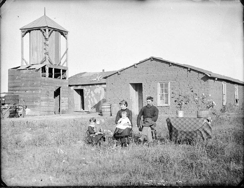
A western New York farmer George Gladden seeking to avoid the long journey to the gristmill wondered whether a mill powered by wind would be a feasible reality on his farm. His attempt to answer this question produced a significant piece of industrial architecture, a vertical windmill, uncommon in its design and perhaps otherwise disappeared in the United States.
The unique features of this windmill include the design of the windwheel and the shutters surrounding it. The wind from one side is directed into the wheel by the open shutters while simultaneously the wind on the other side is directed away from the wheel. As the wind enters it presses against the vanes with considerable force and after passing across the wheel it exerts another force across the vanes as it leaves. Hence the vertical wheel revolves, and with a wind of 20 or 25 miles it could produce 20 horsepower.
Gladden initially had seen the prototype for his windmill near Lincoln, Nebraska in 1888 while visiting relatives. He immediately acquired the rights to build such a mill and purchased the necessary iron parts, and gears. In the fall of 1890 the basement for the structure was excavated and the foundation laid. A year later the mill was completed.
What Gladden had seen in Nebraska may have been what was recorded in the U. S. Patent Office "Official Gazette" on March 19, 1888, patent No. 387424. A patent was awarded to Bernhard Koeppe of Kearncy, Nebraska for a windmill similar in design to Gladden's. The primary difference was that in Koeppe's design the 16 shutters are straight or flat instead of having an angle at the center. Koeppe's wind wheel had eight vanes with a sharp angle at the center instead of the 16 flat vanes Gladden employed. It is probable that the mill built by Gladden was a simplification or variation of the one patented by Koeppe.
Gladden originally equipped his mill with machinery for elevating and grinding grain, an apple grater and press for making cider, a wood turning lathe, and a shop for general repair work. The grain grinding was done on Edward Harrison's "Standard Mill" manufactured in New Haven, Connecticut. Cider making equipment was purchased from the Boomer and Boschert Press Company of Syracuse. Another purchase was a grinder so designed that the grain was fed upward by centrifugal force to the grinding plates. G Madden discovered this device at the 1893 World's Fair in Chicago.
Gladden's vertical windmill, while no longer operational is largely intact with the exception of the vanes which have been removed. It remains as a unique structure and as the ingenious answer to one farmer's search for convenience and increased productivity.
see Charles Gladden, "Unique Windmill,.." MAJOR BIBLIOGRAPHICAL REFERENCESGEOGRAPHICAL DATA
- Gladden, Charles, "Unique Windmill Erected in 1890's still Stands," Randolph Register, Volume 99, Number 15, July 4, 1958.
- Newsletter, Society for Industrial Archeology, Volume one Number 6, Nov., 1972, p, 2.
LATITUDE 42° 14' 06"
LONGITUDE 78° 53' 45"
The technical drawings can also be found in TIMS newsletter 15 (1980), and see also Windmill Hoppers.
The notice about recording of the structure Newsletter, Society for Industrial Archeology, Volume 1 Number 6, Nov 1972, p2Recording/Preservation Needed. A possibly unique feed-grinding wind turbine of 1890 is rapidly deteriorating in Napoli, Cattaraugus Co, (western) NY.The recording took place in summer 1973, and was written up in 1975. In 1980 an appeal was launched to preserve the remains Newsletter, Society for Industrial Archeology, Volume 9 Number 2, March 1980, p4Regulation was by movable shutters (in photo) surrounding rotor. Information: John S Watson, Office of State History, Univ of the State of NY, Bldg 8, Rotterdam Industrial Park, Schenectady, NY 12306.
Wind turbine in jeopardy
In 1883, George Gladden observed a vertical wind turbine in operation on a Nebraska farm. Gladden acquired the rights to build one himself on his farm in western New York state. Gladden's Mill, completed in 1890, is believed to be a variation of one patented by Bernard Koeppe in 1888. (In the Koeppe design, the shutters are flat and the vanes are V-shaped, whereas in Gladden's the opposite is true.)
The Gladden turbine was originally equipped with machinery for elevating and grinding grain, an apple grater and cider press, wood lathe, and shop for general repair work. The vertical wind turbine operated for nearly 40 years, until the thrust bearing at the bottom of the wheel shaft cracked and mill operations ceased.
The Gladden Mill, believed to be the only remaining vertical-axis windmill in the Northeastern U.S., is now threatened. Its owner cares nothing about it and, for a price, wants it moved from his property. Fortunately, the nearby Glover's Mill Energy Center, a conservation and alternative-energy information center headquartered in an 1833 gristmill, has adopted preservation of the Gladden turbine as its cause. The group hopes to buy the turbine and move it to safety. Its owner wants $3,000 for it, and even more money will be needed to move it. General Mills already has generously donated $1000 to the campaign. Additional donations to help save the mill, which was recorded by an emergency team from HAER in 1975, are urgently needed. Contact: Merle Sheffield, Executive Director, Glover's Mill Energy Center, R.D. 2, Box 22, Randolph, N.Y. 14772.
As well as the public appeal for donations, other avenues were explored, and Olean Times Herald, April 1, 1981 records that a grant application originally made in 1980 to the U.S. Department of the Interior for a Heritage Conservation and Recreation Services had resulted in a grant of $20,210. Although the grant could be used to purchase, dismantle, and move the windmill, then prepare the new site, and obtain some replacement materials, it was dependant on being matched by other funds, volunteer labour and services, and donated materials. Gladden Windmill, Inc. had been formed as a non-profit corporation to oversee the project, and eventually operate the windmill as demonstration of windpower open to the public. Hopes were that this additional funding could be found locally, and as the purchase arrangements were being finalized, work was due to start imminently. A further call for volunteers to provide labour, money, advice, services or materials was made, with this being coordinated by the Grover's Mill Energy Center.
The Olean Times Herald, Sept 9, 1981 described that there was an on-site tour of what it called the "Gladden Windmill Rehabilitation Project" organized by The Gladden Windmill, Inc. who were planning the removal, storage, and reconstruction of the mill. A site had been identified on Ronald Cook's farm, on Dempsey Road, Conewango, and the accompanying photo of the tour shows - Charles Barone (representing Sen. Jess J. Present), Assembly Majority Leader Daniel B. Walsh, Ronald Cook, and Steven Lewis, regional officer of the state Office of Parks, Recreation and Historic Preservation, located at Allegany State Park.
The windmill was dismantled at its original site in Pigeon Valley Road, and salvaged by the Glover's Mill Energy Center, East Randolph. However I've found no evidence that it was ever re-erected, and several websites state the dismantled mill is still stored somewhere in Conewango (which could well mean at the Center in East Randolph - the areas overlap). The address of the Glover's Mill given above is a PB Pox, so not very good for locating it! Merle Sheffield who ran the Glover's Mill center died in 1991. (Another eulogy). The Tax Exempt Record for the Glover Mill's Center suggests it may still exist, probably inactive, but is also not very helpful. The center published a cookbook in 1979, which illustrates "Holdridge's Mill, in East Randolph, the present Energy Center", but still doesn't provide an exact location.
This article from the Olean Times Herald, 18/4/2023 carries quite a lot of info about the mill, but it very much relies on quoting other sources, sometimes with inaccuracies creeping in:
| location | |
| state | |
| date | |
| owner | |
| sails |
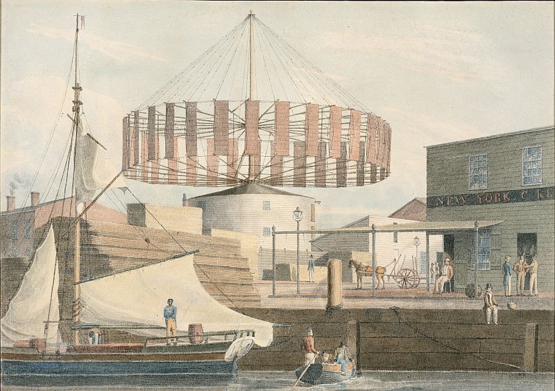
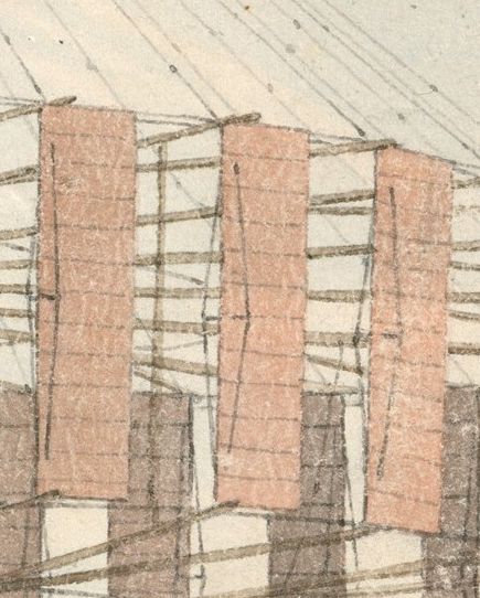
HORIZONTAL WHEEL ...
SIR,-I learn by a communication from New York, that the Rev. Dr. Phoebus, of that city, has constructed a Horizontal Wheel, to be propelled by the wind, the plan of which is extremely simple. There are eight horizontal rays or booms attached to a perpendicular shaft, and on these booms as many sails (in form of a jib) slide out by rings as on the masts of a vessel; each sail is then belayed or fastened (from right to left) to the front ring or travelles of the left-hand sail; and they are suspended so far below the booms as to receive the full impression of the wind - all horizontally. In the revolution of this wheel, it will be readily perceived that the sails turn their backs (or booms) to the wind upon the one side, and form no impediment to the full force of the breeze upon the other side; and they slide out and in with so much convenience, that any length of the sails may be extended at pleasure, or the whole tucked up close at the centre. One, two, or more of these wheels may be attached to the same perpendicular shaft; and it is hardly necessary to say, that they may be applied to almost every description of machinery. The wings or sails may be formed at pleasure, either of canvas, as above mentioned; or, agreeable to Hooper's plan, to open on rollers; or, on the late improvements of Forman's plan, made of thin sheet-iron, to open and close like a Venetian blind.
... Your obedient servant, CLIO.
| location | |
| state | |
| date |
1824 November Saturday 6th (contd): We then went to the City Hall, as Mr. Owen had a letter for Judge Edwards, but he was out of town. We met Judge Irvine who politely shewed us the building built of grey marble brought down [the] Hudson river. ... Another chamber was the City Council room, handsomely and conveniently arranged. ... From the top of the building we had a good view of the City. To the South lies the bay; East, the Sound & Long Island, West, The North or Hudson's river with its wooded & rocky banks; - and North, an extent of low country. The town looked well, and the church spires handsome. I remarked a horizontal windmill & was informed that there are 3 or 4 in the City.The diaries of Donald Macdonald, 1824-1826 - Second Journey
1825 Wednesday 16th November: We reached New York at 1/2 past 5 in the evening. Monday 21st November: After breakfast we all called on Mr. Miesto and went with him to see a horizontal windmill.
| location | |
| name | |
| state | |
| date | |
| sails | |
| building | |
| purpose |
| location | |
| name | |
| state | |
| sails | |
| building |
| location | |
| state | |
| date | |
| owner | |
| designer | |
| purpose |
On the Branch Railroad, five and a quarter miles east of Southampton brings you to the depot of Bridgehampton. Taking the road from this point first south, then east, a good round half mile takes you to the vital centre of this extensive region. This centre was once called Bull's Head, and the name is used to some extent at the present time, but the refined spirit of the day has nearly abolished the frightful appellation. Three large county stores, a hotel, windmill, burying ground, the Presbyterian church, an academy, a district school, and several shops are located nearly within a stone's throw at this focal centre. These are near a point where the main south road, from Montauk Point to Brooklyn is intersected by cross roads from the north side, Sag Harbor, and the ocean.
... About two furlongs west of the village centre stands the Methodist Episcopal church. ...
A little southeast of this, on the road to Sagg, is the agricultural machine shop of C. H. Topping, a self-taught, but successful mechanic and manufacturer. He established the business here in 1862. Besides making repairs on all kinds of agricultural machinery he manufactures ten or twelve horse powers every year. The machinery contained in the shop is driven by a six-horse-power steam engine assisted now and then, when the elements are favorable and circumstances demand it, by a Hubbard patent horizontal wind-mill connected with the shop.
| location | |
| state | |
| date | |
| purpose | |
| designer | |
| sails | |
| building |
The Weather
The Eagle which sits perched on the top of our neighbor Sammis' Windmill, with an unobstructed view from our office window, has not been more variable in its position than have been the phases of the weather during the last week. It has been beautifully mild and spring like, cold damp, foggy and rainy, with a young snow storm for variety.
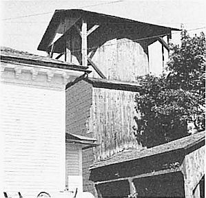
Huntington's Historic Windmill/
(From the Brooklyn Times.)
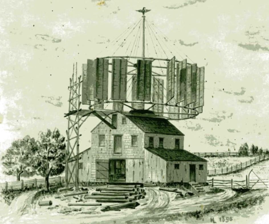
Among the old-time features of the village of Huntington which are fast giving way to the requirements of to-day is one of especial interest, the old windmill which for many years was the most conspicuous building in the village. This has gradually been falling into decay so that at the present time it would hardly be recognized as the old building which was the center of interest thirty or forty years ago, especially for the boys of the place. Nearly all the men of Huntington who were boys at that time remember with not a little pleasure the good times they had riding round on the rims which supported the big sails. There are several Brooklynites now living who joined with the other Huntington lads at that time in the exhilarating and somewhat dangerous sport. The old mill was erected in 1825 by Daniel Sammis. It was then situated at the top of the hill, several hundred feet from its present position and this situation made it the most prominent building in the place. A big wooden eagle which surmounted the tall shaft was an indicator for every one in the village. It was a roughly carved image and is still in existence, the property of Henry Lockwood, a grandson of the original owner. It is to Mr. Lockwood that Huntingtonians are indebted for a restoration of the old building, on paper at least. Probably no one else is able to make a correct picture of the building. Realizing this, and being expert with pencil and brush, although an amateur, Mr. Lockwood has made an excellent drawing of the old structure, which by his kind permission, is reproduced in this paper. The purpose for which the mill was erected is best told in a circular the proprietor issued the next year after he began the work, of which this is a verbatim copy: WINDMILL The public are respectfully informed, that the Saw-mill of the subscriber is now in operation, where he will keep on hand, and for sale, all kinds of wagon timber, white oak plank and boards, ash-plank and white-wood boards, oak lath, chestnut rails and lath for picket fence, white walnut plank for mill cogs: all kinds of timber taken for sawing delivered at the Mill. He will keep pine timbers for piazza columns, and will turn them at the shortest notice: also, he will cut wood screws, and keep on hand turned broom-handles, at two dollars and fifty cents per hundred. Daniel Sammis
Huntington, December 21, 1826. When the mill was built it was the only one of the sort within a circuit of many miles and it is not known by Mr. Sammis' descendants that there was any other anywhere like it. Mr. Sammis was an ingenious man and made the mill from his own design. Whether or not he invented the particular form of wheel used is not definitely known, but it seems likely that he did. Whether he did or not it is certain that great deal of power was derived from the big winged wheel which revolved horizontally, fast or slowly, according to the force of the wind. Huge logs were sawn for ship and house timber and the miller and his employees were kept busy. The building was moved to its present position at the foot of the hill in 1846 or thereabout and it was at this place that it became the favorite play house of the boys who to-day are the most sedate of the business men of Huntington. Every Saturday or other holiday when there was a breeze enough to make the huge wheel revolve the small boys were to be found on the outer rims or on the little slanting, circular roofs over the journals of the big upright shaft. The wheel was about fifty feet in diameter and when a lively breeze was blowing it took a remarkably short time to make the circuit of about 150 feet. Part of this circuit was made at an elevation of forty or fifty-six feet from the ground, clear of the building, according to whether the rider was on the lower or upper rim. The wheel, which gave the power, was suspended from a central shaft 72 feet long, built in two sections. The lower part was of pine. 22 inches in diameter at the bottom and 39 feet long. The upper section was of white oak 33 feet long and 8 inches in diameter at the top. Between the two rims, which were carefully braced, were eighteen sails which filled with wind and gave the power. They were so arranged with weights attached to wires that they "feathered" when coming into the wind and filled when going before it. They swung with sudden jerks and the boys had to be careful in riding on the rims to avoid places where the sails would swing about, or their legs would have been broken by the force of the blows. In spite of the danger that was connected with the practice it is a matter of record that no serious accidents ever occurred there. Mr. Lockwood, in a composition written at a public school many years ago tells of one case, however, that nearly proved fatal. He says: "One fine day in summer as Mr. Sammis was fixing one of the wires that connect the weights and sails, there happened to be a pretty lively breeze at the time which made the mill go. He was standing on the plank which leads from the building to the scaffold when I pulled one of the loose wires, which caught under his chin and would have been the cause of his death if there had been no hand railing to keep him from falling over backwards. He talked to me about it and I felt very sorry for my conduct." Charles Lockwood, a brother of the writer of the composition, was the means of saving the life of a companion at the same spot, which probably recompensed for the damage Henry did. He was walking up the [unreadable - but see later repeat] dangling from the wheel, came round. Starkin didn't see the wire and it caught him under the chin. He instinctively reached up both hands and grasped the wire. He was dragged off the runway and carried around the circuit. When he came bark to the starting point he was too frightened or dazed to drop and around he went again, his body dragging over the runway. He went around the third time and was just about exhausted when he reached the runway and Lockwood seized him and pulled him off the wire. The upper part of the mill was blown down in a heavy gale about the year 1867 and since then several changes have been made in the old building and it has fallen into disuse. The use of power in the building was discontinued when the wheel was blown off. [unreadable] however, and not a few of the older Huntingtonians will be glad Mr Lockwood has preserved the [unreadable] in the sketch he made.
Old Sammis Windmill Blown Down. During the heavy blow last Saturday night the old Sammis windmill at the rear of the LONG-ISLANDER office blew down. The structure had been going to decay for a number of years, but a few weeks ago when Joseph Sammis was here from Belleville, N. J., he said he intended to fix it up so as to make use of it. Nearly all the men of Huntington who were boys about the village fifty years ago well remember the good times they had riding around on the rims which supported the big sails, as shown by the cut. The picture was made from a drawing executed by the late Henry Lockwood. The old mill was erected in 1825 by Daniel Sammis. It was then situated at the top of the hill, several hundred feet from its present position, and this situation made it the most prominent building in the place. A big wooden eagle which surmounted the tall shaft was an indicator for everyone in the village. It was a roughly carved image and is still in existence, the property of Everett Lockwood, a great grandson of the original owner. The purpose for which the mill was erected is best told in a circular the proprietor issued the next year after he began the work, of which this is a verbatim copy: WIND MILL. The public are respectfully informed, that the Saw - Mill of the subscriber is now in operation, where he will keep on hand, and for sale, all kinds of wagon timber, white oak plank and boards, ash plank and whitewood boards, oak lath, chestnut rails and lath for picket fence, white walnut plank for mill cogs, all kinds of timber taken for sawing delivered at the Mill. He will keep timbers for piazza columns, and will turn them at the shortest notice; also, he will cut wood screws, and keep on hand turned broom-handles, at two dollars and fifty cents per hundred. DANIEL SAMMIS.
Huntington, December 21, 1826. When the mill was built it was the only one of the sort within a circuit of many miles and it is not known by Mr. Sammis' descendants that there was any other anywhere like it. Mr. Sammis was an ingenius man and made the mill from his own designs. Whether or not [he invented] the particular form of wheel used is not definitely known, but it seems likely that he did. Whether he did or not it is certain that a great deal of power was derived from the big winged wheel, which revolved horizontally, fast or slow, according to the force of the wind. Huge logs were sawn for ship and house timber and the miller and the employers were kept busy. The building was moved to its present position in 1846 or thereabout and it was at this place that it became the playhouse of the boys who to-day are the most sedate of the business men of Huntington. Every Saturday or other holiday when there was breeze enough to make the huge wheel revolve the small boys were to be found on the outer rims or on the little slanting, circular roofs over the journals of the big upright shaft. The wheel was about fifty feet in diameter and when a lively breeze was blowing it took a remarkably short time to make the circuit of about 150 feet. Part of this circuit was made at an elevation of forty or fifty-six feet from the ground, clear of the building, according to whether the rider was in the lower or upper rim. The wheel, which gave the power, was suspended from a central shaft, 72 feet long, built in two sections. The lower part was of pine, 22 inches in diameter at the bottom and 39 feet long. The upper section was of white oak 33 feet long and 8 inches in diameter at the top. Between the two rims, which were carefully braced, were eighteen sails which filled with wind and gave the power. They were so arranged with weights attached to wires that they "feathered" when coming into the wind and filled when going before it. They swung with sudden jerks and the boys had to be careful in riding on the rim to avoid places where the sails would swing about, or their legs would have been broken by the force of the blows. In spite of the danger that was connected with the practise it is a matter of record that no serious accidents ever occurred there. Mr. Lockwood, in a composition written at the public school many years ago, tells of one case, however, that nearly proved fatal. He says: "One fine day in summer as Mr. Sammis was fixing one of the wires that connects the weights and sails, there happened to be a pretty lively breeze at the time which made the mill go. He was standing on the plank which leads from the building to the scaffold when I pulled one of the loose wires, which caught under his chin and would have been the cause of his death if there had been no hand railing to keep him from falling over backwards. He talked to me about it and I felt very sorry for my conduct." Charles Lockwood, a brother of the writer of the composition, was the means of saving the life of a companion at the same spot, which probably recompensed for the damage Henry did. He was walking up the runway as usual with George Starkin, who was not familiar with the apparatus, and ducked when a loose wire, dangling from the wheel, came around. Starkin didn't see the wire and it caught him under the chin. He instinctively reached up with both hands and grasped the wire. He was dragged off the runway and carried around the circuit. When he came back to the starting point he was too frightened or dazed to drop and around he went again, his body dragging over the runway. He went around the third time and was just about exhausted when he reached the runway and Lockwood seized him and pulled him off the wire. The upper part of the mill was blown down in a heavy gale about the year 1867 and since then several changes have been made in the old mill building and it has fallen into disuse. The use of power in the building was discontinued when the wheel was blown off.
Warren G. Sammis' horse became suddenly frightened in his wood yard last Friday noon and suddenly started off on a run. Warren Sammis Jr., who was in the wagon at the time was unable to control the animal and was thrown out, but fortunately was only severely bruised. The horse ran out of the yard and finally into the lane leading to the windmill, where he was captured. The wagon was badly smashed.
The strawberry patches of Messrs Reed and Fannell on New York avenue and in the field back of the old windmill, comprising about two acres in all, now present a very handsome appearance. There will doubtless be a large crop. Their plants are of 22 varieties, including such prominent kinds as the Sharpless, Creseent, Bidwell's, Jersey Queen, Mauchester, Hervey Davis, Warren, Longfellow, Jas. Viek and Big Bob. This assortment will enable them to supply the market for a long season. This is a worthy enterprise and we hope the example set by these gentlemen will iduce our farmers to embark in similar enterprises which will pay better than old fashioned farming.
HUNTINGTON METHODISM
LOCAL CHURCH HAS USEFUL HISTORY OF OVER ONE HUNDRED YEARS.
...
Before the church was built, meetings were held for a while in Daniel Sammis' house and, after the windmill was built in 1825, services were held there until the church was completed.
...
The first church was a severely simple structure. It was planned by Daniel Sammis, who at that time conducted a sawmill. After the subscriptions had been paid in - they ranged from 6 cents to $50, the last named sum having been subscribed by Christopher Ming, a moneyed man of the day, the building was commenced. Mr. Sammis was the leading factor of the event. He built the pulpit, turned the high wooden candlesticks that stood on both sides of the reading desk, and made the bench with turned legs that stood behind the pulpit in place of a chair.
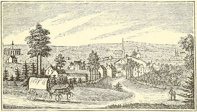
The Long Island Historical Association provides a few more details about this mill:Western view of Huntington Village.
The above sketch taken from Barber & Howe's Historical Sketch of New York State, gives a good idea of how this village looked in 1830. Note the curious windmill which was built in 1825, the central shaft was 72 feet high, and was propelled by eighteen sails arranged between the two rims. The top of this structure was blown down in a heavy gale about 1867.
| location | |
| name | |
| state | |
| designer | |
| date | |
| purpose |
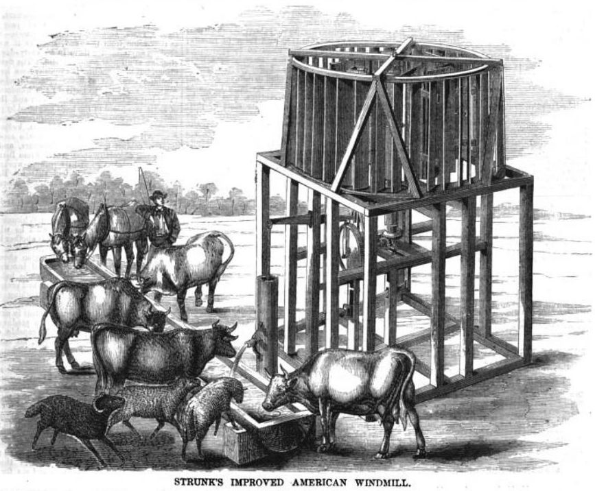
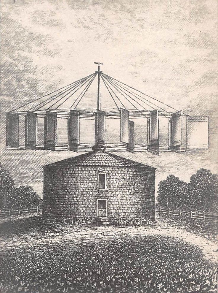
There's a short query from someone a few weeks later on the device English Mechanic and mirror of science and art, Aug 2, 1867Strunk's improved American Windmill.
Although the force of wind is an unreliable motor for some manufacturing purposes, yet it affords a cheap and ready means for driving machines the proper action of which does not depend upon absolute steadiness of motion. It has been and is-still extensively employed in some sections of this country for pumping and other purposes. For service, at railway stations and on farms, it is a valuable aid to man. Much of this value, however, depends upon the plan and construction of the wind wheel or mill. The one which we illustrate from the pages of the "Scientific American" appears to be constructed on right principles and is calculated to work satisfactorily under all circumstances, whatever the force or direction of the wind. It is a horizontal wheel, mounted on a vertical shaft, and having eight fans or buckets hinged at their inner edge on uprights secured to radial arms. These fans are connected in pairs by pivotted iron rods so as to insure each one of each pair moving together when the angles of their inclination are changed. One fan of each pair has also a projecting brace, which connects by an iron rod with a bell crank lever on an upright bar near the central shaft. From this lever a rod passes down to an enveloping and sliding collar on the upright shaft. There are four of these bell cranks, one to each pair of fans, and by the raising or lowering of the sliding collar the fans are set at any required angle to suit the force of the wind. This collar is raised or lowered by a lever having a sliding weight by which its action on the collar can be regulated. This lever will also operate a lever brake in case of a gale - being self-operating under great pressure - which bears upon the rim of the fly-wheel. At the foot of the vertical shaft is a bevelled gear engaging with another on a horizontal shaft, which carries a balance wheel having a crank to operate a walking beam for pumping purposes. The wind wheel is inclosed in a circular frame having upright slats set at an angle, to divert or guide the current of air upon the fans, giving a rotary motion always in one direction.
The labour of raising water from wells for cattle is an onerous one. Where all the water used must be obtained from wells sometimes of great depth - one hundred and more feet, as on the prairies - the task is no small one. It has been estimated that cattle ordinarily consume fourteen gallons per head daily. Twenty head of cattle - not a large number on a farm - will therefore consume about three thousand barrels of water annually. In such cases an apparatus like that illustrated in the engraving would be invaluable, and also for railroads where the water for the locomotives is drawn from wells.
The inventor says that this machine will work equally well in a gale as in a moderate wind.
At the late State Fair of Wisconsin one of these machines pumped nearly all the water used for the stock on the grounds, from a depth of more than one hundred feet. The lower part of the structure can be boarded in and roofed, making a convenient granary, store-house, or carriage shed; or the wheel can be erected upon any building.
This windmill has been patented by F. and D. Strunk, of Janesville, Wisconsin, U.S., America.
AMERICAN WINDMILL, - In our journal of June 28 there was a short paragraph and sketch of "Strunk's Improved American Windmill," can any render inform me if they answer as well as the tower or post mill for corn grinding - STRAM POWER.D Strunk was Daniel Strunk. He also got other patents, including for a seeding machine (173711) in 1875, and a harvester in 1877.
| location | |
| name | |
| state | |
| date | |
| purpose |
THAT SUMMIT WINDMILL
Portland, Maine, Aug. 9, 1899.
To the Editor of Among the Clouds :-
I read the letter of Mrs. Maclaren in Monday's edition of Among the Clouds with a great deal of interest.
I have a love, nay, almost a veneration for the White Mountains, that I cannot shake off even were I so disposed, and any article that I see relating to them I eagerly devour. I remember "Little Jessie" very distinctly and her father also.
I was employed on the Summit House as carpenter when the addition was being built, and of course saw a great deal of them, and a brighter or happier girl would be hard to find. She was the pet of all the men and her every wish was granted, as none could resist her pleading eyes and winning ways.
She writes of her father relating humorous stories which brings to my mind one that I was an eye witness to. Mr. Aiken had a horizontal windmill built at his shop in Franklin, N. H. to be used for pumping water from the tank near Lizzie Bourne's monument to the Summit House. It was brought to the Base where the frame was made in which it was to run, and then loaded on to a flat car. Now the frame being so much wider than the car it was necessary that some one should ride on the top, so as to signal the engineer in case it was liable to hit any rocks on one side or telegraph poles on the other. This man who was on the lookout was (I guess I won't give him away as he is still with the Mount Washington Railway and might not like it.) standing on top of the windmill, and when crossing Jacob's Ladder gust of wind struck it, and it commenced to revolve with amazing rapidity. You have probably seen a squirrel in a revolving cage, but it could not begin to beat time as this man did. It was Hobson's choice with him, either walk or fly off on a tangent, and the way he sprinted was a sight to behold.
The mill eventually was put in position at the tank, and then came the piping, and as it was in the height of the season this had to be done when the business of the road would admit of it. Sunday was the day chosen, but the proprietor of the hotel being of a pious turn of mind objected to breaking the Sabbath and hoped it would prove a failure, and as a matter of fact there was not wind enough on the Summit to blow out a match for twelve days.
I recollect the remark made by one of the men that if putting up a windmill on Sunday kept the wind from blowing for two weeks, if we got six more they would insure calm weather all summer.
S. H. M.
| location | |
| state | |
| date | |
| sails | |
| building |
| location | |
| state | |
| date | |
| designer | |
| sails | |
| note |
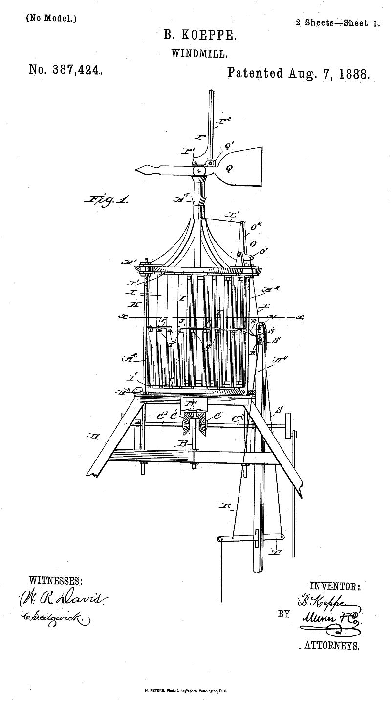
Many patent applications were made for theoretical devices, which never saw the light of day in anything beyond perhaps a model form. However, Bernard Koeppe's patent was not accompanied by a model - which I'm pretty sure was because he'd actually already constructed the windmill that he was patenting. Various accounts (specifically relating to the Gladden windmill, Napoli) say that Koeppe's windmill was seen near Lincoln, Nebraska.
US Patent 387424, Windmill, Bernard Koeppe, 1888(No Model.) 2 Sheets B. KOEPPE. WINDMILL, No. 387,424, Patented Aug. 7, 1888.
UNITED STATES PATENT OFFICE.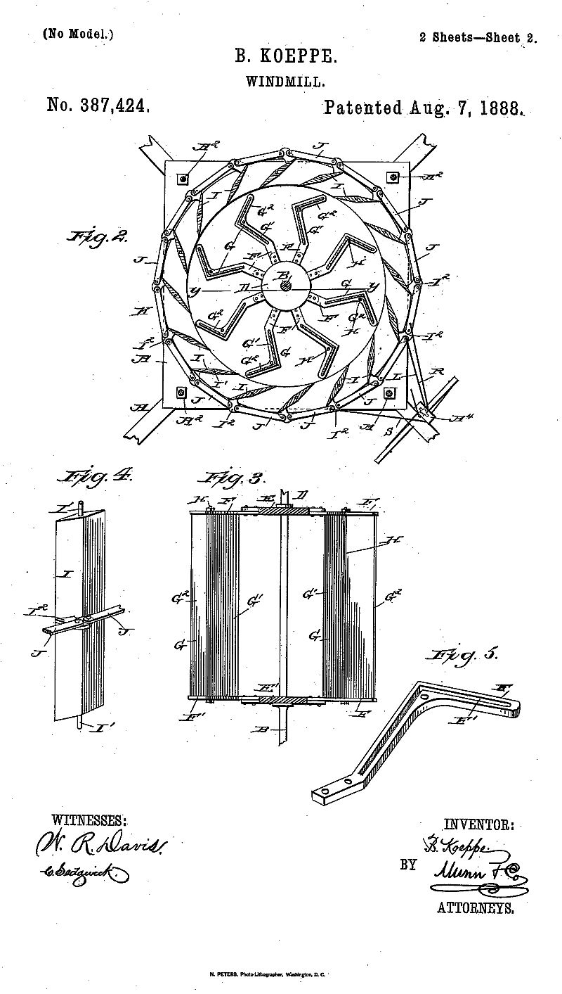
BERNHARD KOEPPE, OF KEARNEY, NEBRASKA.
WINDMILL
SPECIFICATION forming part of Letters Patent No. 387,424, dated August 7, 1888.
Application filed March 19, 1888, Serial No. 267,657. (No model.)
To all whom, it may concern:
Be it known that I, BERNEARD KOEPPE, of Kearney, in the county of Buffalo and State of Nebraska, have invented a new and Improved Windmill, of which the following is a full, clear, and exact description.
The object of the invention is to provide a new and improved windmill which is simple and durable in construction, very effective in operation, and automatically governed in regard to its speed.
The invention consists of a wind-wheel having angular wings and held inclosed in a casing composed of sides adapted to swing open and shut.
The invention also consists of certain parts and details and combinations of the same, as will be fully described hereinafter, and then pointed out in the claims.
Reference is to be had to the accompanying drawings, forming a part of this specification, in which similar letters of reference indicate corresponding parts in all the figures.
Figure 1 is a side elevation of the improvement. Fig. 2 is an enlarged plan view of the same on the line x x of Fig. 1. Fig. 3 is a sectional side elevation of the wind-wheel on the line y y of Fig. 2. Fig. 4 is a perspective view of one of the sides of the casing, and Fig. 5 is a perspective view of one of the wind wheel arms supporting the wind-wheel wings.
A suitably-constructed frame, A, supports at its upper end a head, A', by means of bolts A2, secured in any suitable manner to the upper part of the frame A. In suitable bearings on the main frame A and in the said head A' is mounted to rotate a vertical shaft, B, carrying near its lower end a bevel gear-wheel, B', meshing at opposite sides into bevel gear wheels C and C', fastened, respectively, to the shafts C2 and C3, mounted to rotate in suitable bearings on the main frame A and connected in any suitable manner with the mechanism to be driven by the wind-wheel.
On the shaft B, between the head A' and the top plate, A3, of the frame A, is secured a wind wheel, D, provided near its upper end with a disk, E, and near its lower end with a similar disk, E', the said two disks, E and E', being rigidly secured on the main shaft B. On the disks E and E' are secured the angular or shaped arms F, which extend horizontally and outward in the mannershown in Fig. 2. Each of the arms F is provided with an angular groove, F', and the arms on the upper and lower disks, E and E', correspond with each other, so that the grooves F' are turned toward each other in two corresponding arms in the upper and lower disks, E and E'.
In each corresponding set of arms F is placed a wing, G, consisting of two plates, G' and G2, jointed together at an angle and fitting into the angular grooves F' of the arms F at their top and bottom ends. The wings G are held securely in place by being fitted at their ends into the angular grooves of the arms F of the disks E and E'. Two arms, F, of the upper and lower disks E and E' are also connected with each other and strengthened by screw-rods H, passing through suitable apertures in the corners of the angular arms F, and provided with nuts on the outside screwing against the tops and bottoms of the two corresponding arms F. A very strong wind-wheel is thus built.
The wind-wheel D is inclosed on its periphery in a casing, K, consisting, principally, of a number of sides, I, (shown plainly in Fig. 4,) each side being provided at its ends with trunnions I', fitting in corresponding apertures in the head A' and the top plate, A3, of the frame A, so that the said sides I can turn freely. The sides I are placed in such a relative position to each other that when the sides are closed the respective ends overlap each other, thereby inclosing the periphery of the wind-wheel D completely, so that no wind can get to the wings of the said wind-wheel. On each of the sides I, on the outside, is formed a lug, I2, with which are pivotally connected the arms J, extending from each lug to the next following lug. As the sides I are arranged in a circle around the wind-wheel D, it will be seen that two arms, J, are pivotally connected with each lug I2, as is plainly shown in Fig. 2. The sides I are preferably diamond-shaped in Cross-section, so as to permit an easy entrance of the wind to the wind-wheel when the sides are opened.
To one of the arms J is secured one end of a rope, L, passing under a pulley, N, mounted to rotate in the upper end of a post, A4, secured to one side of the main frame A. The rope L, after passing under the pulley N, extends upward and connects with the end O' of a bell-crank lever, O, fulcrumed on top of the head A' and connected by its other arm, O2, with one end of a rope, L'. The latter extends inward and passes to the center of a hollow rod, A5, secured to the top of the head A', and then the rope L' passes upward and through the said hollow rod A5 and is secured to one end of a bell-crank lever, P, carrying to on its other arm a wing, P'. The bell-crank lever P is pivotally connected with a lug, Q', formed on a vane, Q, held to turn on the upper end of the rod A5, so that when the said vane Q turns, it carries with it the bell-crank lever P and its wing P2. To another arm, J, is secured one end of a rope, R, which passes over a pulley, R', mounted in the upper end of the post A4, and then the said rope extends downward and is secured to one end of a lever, T, pivoted in the lower part of the post A4. To a link on the other side of the post A4 is secured one end of a rope, S, which passes over a pulley, S', in the upper part of the post A4, and then the said rope S extends downward and is securrd to the other end of the lever T, before mentioned.
The operation is as follows: When the wind-wheel is in the position shown in Figs, 1 and 2, the sides I of the casing K are open, so that the wind coming from any direction can pass through the said open sides I and pass to the angular wings G of the wind-wheel D. The wind is guided into the wind-wheel by the relative position of the said arms I, so that the full force of the wind is concentrated on the angular wings G of the wind-wheel, whereby the latter is rotated, and imparts its rotary motion to the main shaft B, which in any suitable manner transmits it to the mechanism to be operated. When the wind increases in velocity and causes the wind-wheel D to run above the normal speed, the increased velocity of the wind acting on the wing P2 of the bell-crank lever P causes the latter to swing so that the wing P2 moves downward, thereby swinging the other arm, P', of the bell-crank lever P upward. A pull is thus exerted by the arm P' on the rope L', whereby the arm O2 of the bell-crank lever O is swung inward, and the other arm, O', of the said bell-crank lever is swung upward, exerting a pull on the rope L. The latter is thus drawn upward and forward, thereby exerting a forward pull on its respective arm J, which causes the sides I to close, whereby the wind is prevented from entering between the said sides I and passing to the wind-wheel. The sides I of the casing K can also be opened or closed by the operator by moving the lever T, so that either the rope R is pulled downward, thereby closing the sides I, or the rope S is moved downward, so that the sides I are opened as the said ropes R and S are connected to arms J at opposite sides of the post A4. Thus it will be seen that the operator is fully enabled to admit any amount of wind to the wind-wheel D so as to increase or decrease its speed.
Having thus described my invention, what I claim as new, and desire to secure by Letters Patent, is -
1. In a windmill, a casing inclosing the wind-wheel and composed of sides held to swing and connected with each other by arms, in combination with two ropes connected at their ends with two of the said arms, a fixed arm carrying pulleys over which pass said ropes coming from opposite directions, and a lever fulcrumed in the said post and to which said ropes are connected at opposite ends, substantially as shown and described.
2. In a windmill, the combination, with a wind-wheel having angular wings, of a casing inclosing the wind-wheel and composed of sides held to swing and connected with each other by arms, two ropes connected at their ends with two of the said arms, a fixed arm carrying pulleys over which pass the said ropes coming from opposite directions, and a lever fulcrumed in the said post and to which the said ropes are connected at opposite ends, substantially as shown and described.
BERNEHARD KOEPPE.
Witnesses:
JOHN D. LEWENSTEIN,
JOSEPH. A. FLORANG.
| location | |
| state | |
| date | |
| designer | |
| purpose |
| location | |
| name | |
| state | |
| date | |
| designer | |
| sails | |
| purpose | |
| gps | |
| note |
| location | |
| name | |
| state | |
| designer | |
| date | |
| purpose | |
| sails |
The horizontal turbine crops up pictured in many a Disney Blog - as it's at an appropriate height it's a popular place to for seasonal decoration such as at Easter or Halloween. I'm sure it must be an Instagram spot as well! Blogs include
| location | |
| state | |
| date | |
| purpose | |
| designer |
In the files of the energy offices in Washington, D. C. and in Hartford there are frequent references to the name of Sherman Chase of Kent, Connecticut. He is known as the inventor of a new type of windmill which will power a generator even in a very light breeze. No exterior rotor blades. It is so responsive that it will work from heat as well as wind. Even on a quiet day, reflected sunlight will keep it running. Sherm still is working to improve its efficiency. One of these days the right to mass-produce it may be negotiated.
| location | |
| name | |
| state | |
| date | |
| purpose | |
| designer |
| location | |
| state | |
| millid | us |
| Last generated 30/06/2026 | Text and images © Mark Berry, 1997-2026 - |