Other coverage of horizontal windmills:
Although there is rich stream of references and illustrations of horizontal windmills, many of them probably never proceeded past the design stage. This page covers such designs, drawings, and proposals, and other references to horizontal windmills that cannot be traced to even an approximate location.
Contents
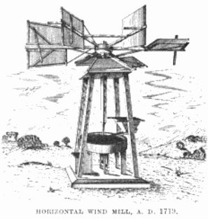
It shows a six bladed device, attached to a vertical shaft, being blown round by a dismembered head. There is no mechanism to cause the wind to only act on one side of the device, and by most edges the blades appear flat, though the top edge of the one in the direct path of the wind might have a slight curve to it. At the lower end of the shaft, a small diameter lantern gear engages with a much larger toothed wheel, giving a gearing down effect, and a rope that passes over the large wheel disappears into a large cylinder, perhaps indicating this being used to draw water, though there is no indication of exactly how this would occur. Around the rest of the page are seemingly unconnected smaller drawings, showing for example knights on horseback.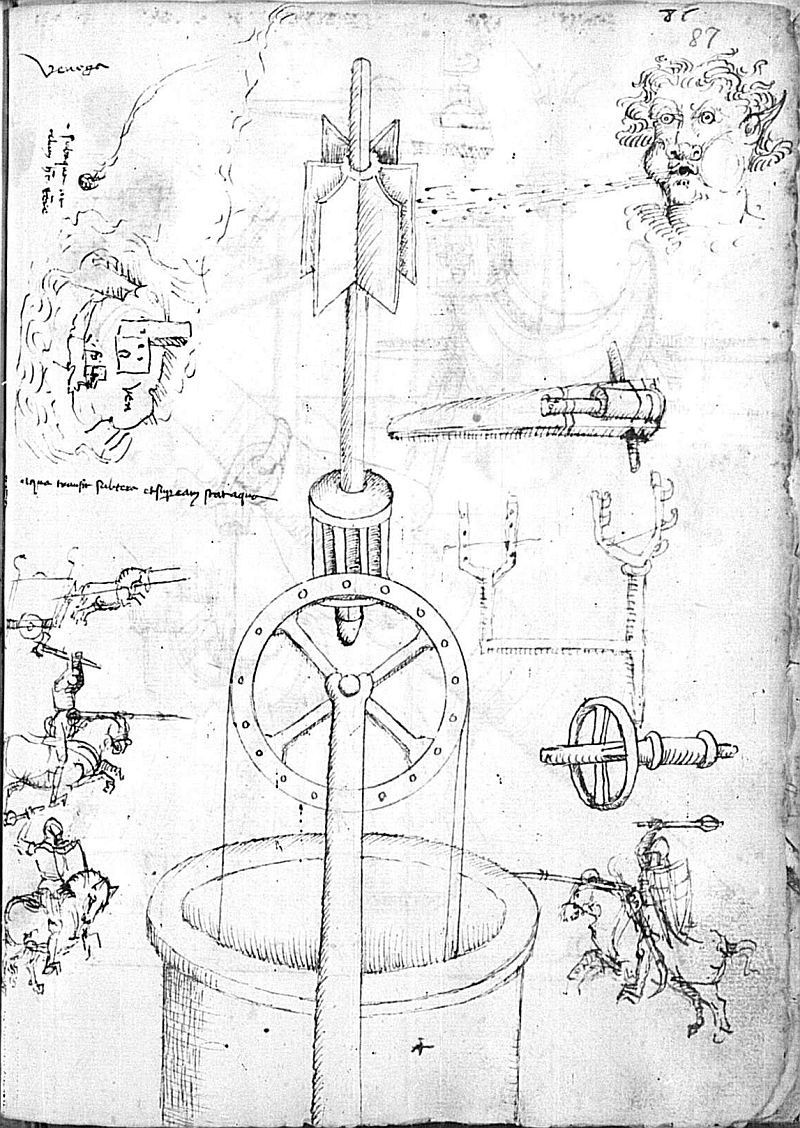
The rest of the notebook has many other illustrations of mills, powered by water, horses, and even a human treadmill, doing various work including grinding, working bellows, and raising water.
Discussed at length in Reforming Windmills: Gerhard Westerburg, Theologian and Inventor (1486–1558).[extremely rough, mostly OCR transcription, by a non-German speaker!]Eyn Wunderbarliche Roß windmull / vor nie mehr gefehen Roß windmul ist meyn redter nam/ gcben mulmerd ic omb dreiben Fan/ Mit vierzig fugeln fdnel rno bbend Durch alle minde werdrmbgemendc Jd fibleiff /fege bolt/follezfdneide barbey 2ad Oly pud ftof puluer fren/ Diefe focs werd ic off Der croen ban pen bab icb pier Eorn mullen ftan Wanmindt gebricht/bolic feche pferbe ondenidyombgedricben merdc mepn bauf ift ticffond ftard fundirt Coift feun fturmmindt der mic jrit Mod bobe bem nod fennoce madt Für ftedc ono fdlof bin id erdache Jnmunder groffen fturm minden Ran mideon junger fnab bamingen Go icin nollemlauffbin befletdc Dic fegelfthnur fennd baldt bereit Billid werdid wunderlid genanc Poins gleuden ift in Eennemlandc Diemit Roß/pno minden malen fan Doncunem fpillradt pinb jugabn Do man fdrcib funffien bundert jar Funffonorirgig/mardidoffenbar Crfundenerftin Oft :Frieflandt/ nder Gtabe die Emden ift genane Dic Burger dafelbft all gå mol Die Eennen meynen mepfter wol Bocc bab emig lob pnd preyf Der menne menfter folce bat endmenft Bcorndtsu Collenbey Sant Cupuo
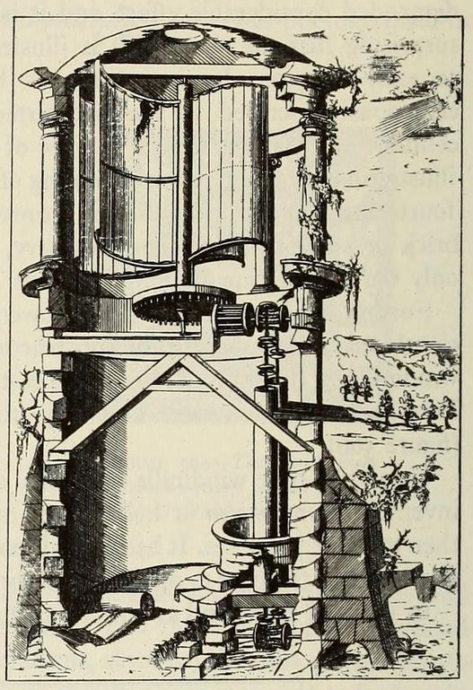
This monumental work Machinae novae Favsti Verantii siceni, Fausto Veranzio, 1595 contains more early illustrations of horizontal windmills (and plenty of other mills of other types).
The text on the illustrations is in Latin, but the descriptive text is repeated in 3 languages - Latin, Italian, and French. It does not always line up with the included illustrations - the paragraphs of text labelled VIII are for a portable iron mill, which is included on the plate labelled 7 (not 8).
Plate VIIIPlate IX8. Mill driven by sails
Plate X9. Mill with triangular arms
Plate XI10. Mill with hinged sails
Plate XII11. Mill with mobile roof
Plate XIII12. Mill with square tower
13. Mill with round tower
John Winthrop, Jr., is one of the most interesting, attractive and picturesque personalities in our early colonial history. ... January 18, 1629, he writes that he has a perfect plan with complete dimensions of the fort at Colchester. He also gives a full account of a horizontal wind-mill which he has invented and which he thinks will be very useful in a new country. This invention seems however never to have gotten further.The letter from John Winthrow Jr to his father was published in the Collections of the Massachusetts Historical Society, Vol VIII 5th Series, 1882
JOHN WINTHROP, JR., TO HIS FATHER.
To the wor[shipfu]ll his very loving father John Winthrop Esq. at Mr. Downings house in Peterborough Court over ag[ains]t the Conduit in Fleet Street, London.
S[i]r, My humble duty remembred, I receyved your letters, reioycing much to understand of the continuance of your welfare. Wee are heere (God be praised) all in good health. I am glad you have made an end w[i]th my brothers businesse upon so good termes; he & she are both very glad of it: it would have bred much trouble if it could not now have bene put of, besides what hinderance it would have bene to themselves. I was last weeke at Colchester w[i]th Mr. Heath the Kinges workman, who made the fort at Langer Point. I have now a perfect plot thereof, w[i]th the dementions of the whole & parts. I will have it ready ag[ains]t you come downe.
I have now made a rude modell (as only to shew that it is feasable) of that wind motion, w[hi]ch I tould you of, then only imagining it speculatively, but now have seene the experience of it, and doe affirme that an instrument may be made to move w[i]th the wind horizontally to equall if not to exceed the ordinary verticall motion of the windmill sailes, both in swiftnesse & force: for the wings of it (w[hi]ch may be eyther 4, 6, or 8, or as many as the workman will) in the one semicircle shalbe allwaies w[i]th their broad superficies oposite to the wind, the other semicircle (allowing only such bredth as for strength the timbers of the wings shall require) shall be in respect only liniarily oposite to the same, & where there is any broad superficies pressed upon by the violence of winds we may conceive the force it carrieth by the great weight that it moveth, as ships, &c., & where it is placed upon a center, & farr distant from the same, we may iudge w[i]th what violence it would whirle round, by the effect it worketh upon ships sailing close by a wind (w[hi]ch tendeth towards a round motion, save that it continually as it declineth changeth his center, & falleth on a new one) that sometyme through the force of it, it oversetteth them though poised w[i]th reasonable weight. Swiftnesse must needs proceed proportionably from force. I conceive it may be aplied to many laborious uses as any kind of mills, corne mills, saw mills &c., & I thinke a cornemill of this to performe w[i]th the ordinary verticall mills may be made for little more cost than a good horse mill, & so may hold proportionably in the other sorts, as saw mills, oyle mills, &c., w[hi]ch are not made eyther for wind or water w[i]thout great cost; for this may be made as low as the workman will, whereas the verticall mills must be made very highe, w[hi]ch maketh them so chargeable. And one spetiall property wilbe in them, that they allwaies stand right for the wind wheresoever it bloweth. If there may be made any use of it, I desire New England should reape the benefit for whose sake it was invented. Et soli Deo gloria.
Heere was to day a youth from Polsted to be enterteyned for New England, but knowing you were full I bid him not loose his labour to come any more to speake w[i]th you, etc. I pray remember my duty & love to my Uncle & Aunt Downing, w[i]th my love to my cosens & freinds. Thus desiring your blessing & praiers, I comend you to Gods protection & rest
Your obedient sonne,
JOHN WINTHROP.
Grot[on]. Jan: 18, 1629[-30.]
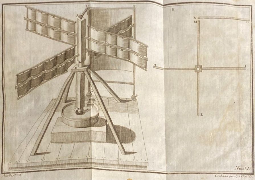
MOULIN HORISONTAL INVENTE PAR M. COUPLET DE L'ACADEMIE ROYALE DES SCIENCES.Approximate Translation:
Avant 1699. No.30.
Ce Moulin est composé d un arbre vertical ABC soûtenu en B par un colet dans lequel il peut tourner librement. La partie AB est garnie de quatre aîles de Moulin à vent ordinaire & posées les unes sur les autres; ces aîles doivent être semblables à celles dont on se sert; c'est à dire de la même longueur, & présenter au vent une grande surface.
La meule est fixée à l'extrémité C & ne différe en rien des autres meules.
Le chassis DEFG, que l'on peut appeller gouvernail, est fait de bois couvert de toile dans une bonne partie de sa hauteur: sa largeur est un peu plus grande que la longueur des aîles; il tient à l'arbre par la piéce AD vuë en raccourci dans cette Figure, qui cependant doit être plus longue que les aîles. Les pieds GF sont garnis de roulettes, afin de faciliter le mouvement de ce gouvernail, qui doit tourner sur la plate-forme tout-au-tour du Moulin lorsque l'on veut l'orienter. Son usage est de s'opposer au vent, pour qu'il n'y ait qu'une seule aîle de frappée, ce qui se concevra par le plan HILM des quatre aîles. NO est le plan du gouvernail qui doit tourner, comme on l'a déja dit autour du centre P. Que l'on suppose à présent que le vent vienne de la partie R pour frapper sur la surface de l'aîle HP; s'il n'y avoit rien qui s'opposat au vent, il y auroit une force égale de part & d'autre sur les deux aîles HP, PI, & tout étant en équilibre le moulin ne tourne roit pas, aulieu que le gouvernail étant disposé pareillement devant l'aîle PI, l'aîle HP recevra toute l'impulsion dont le vent sera capable, & il n'y aura du côté PI qu'un fort petit obstacle qui s'opposera à la force imprimée, puisque le gouvernail NO soûtiendra lui-même une force égale à celle qui frappe l'aîle HP, par ce moyen le Moulin pourra produire l'effet demandé.
Les avantages de cette construction consistent, 1. Dans la suppression de la rouë dentée, & de la lanterne, ce qui produira une exécution plus facile, & de moindre dépense. 2. De pouvoir tourner à toutes fortes de vents. 3. De trouver plus de facilité à être orienté n'ayant qu'un chassis à mouvoir, aulieu de tourner un Moulin tout entier, ou du moins un comble qui est toûjours fort pesant. D'ailleurs il resteroit à sçavoir s'il n'y auroit point quelques difficultés par rapport à la solidité, & si cette espéce de Moulin ne seroit pas plus sujet que les autres à être renversé dans les grands vents.
HORIZONTAL WINDMILL INVENTED BY Mr. COUPLET OF THE ROYAL ACADEMY OF SCIENCE.
Before 1699. No. 30
This Mill is composed of a vertical shaft ABC supported at B by a collar in which it can rotate freely. Part AB is fitted with four ordinary windmill sails, laid on top of each other; these sails must be similar to those used; that is, of the same length, and presenting to the wind a great surface.
The millstone is fixed at the end C & does not differ from other millstones.
The chassis DEFG, which can be called the cover, is made of wood covered with canvas for much of its height: its width is a little greater than the length of the sails; it holds to the shaft by the piece AD seen as a shortcut in this Figure, which however must be longer than the sails. The feet GF are fitted with wheels, in order to facilitate the movement of this cover, which must rotate on the all-around platform of the mill when you want to orient it. Its use is to block the wind, so that there is only one struck sail, which will be conceived by the HILM plan of the four sails. NO is the plan of the cover that must turn, as has already been said around the center P. Let it be assumed now that the wind comes from the part R to strike on the surface of the sail HP; if there is nothing that is blocking the wind, there will be an equal force on both sides of the two HP, PI, and everything being in equilibrium the mill will not be a powerful force, in which the cover will be arranged similarly before the sail PI, the sail will be equal to the sail, PI, and all being in equilibrium the mill will be the right to the air.
The advantages of this construction consist, 1. The removal of the toothed wheel and lantern, which means an easier and less expensive build. 2. To be able to operate in all wind strengths. 3. To find it easier to be oriented having only a frame to move, instead of turning an entire mill, or at a minimum a heavy cap. Moreover, it remains to know whether there would be no difficulty in relation to the solidity, and whether this type of mill would not be more subject than the others to be overthrown in the high winds.
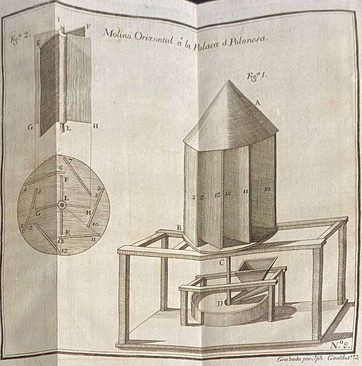
MOULIN HORISONTAL OU A LA POLONOISE INVENTE PAR M. DU QUET.Approximate translation
Avant 1699. N0. 31
Le Moulin horizontal AB est composé de plusieurs cloisons 2, 3, 13, 12, 11, 10, posées obliquement sur un plan circulaire, de maniére que l'intervale de ces cloisons permette au vent de passer pour frapper sur une vanne IL formée de quatre aîles G, H, E, F. Cette vanne étant posée verticalement au centre de la tour, on prolonge son arbre CD, auquel l'on fixe la meule, qui ne différe en rien des meules ordinaires non plus que les autres parties du Moulin. Cette vanne ayant la liberté de tourner sur elle même l'on voit par la disposition des cloisons 9, 10, 11, 12, 13, 3, 2, 5, 4, 6, 7, 8; qu'elles laissent entr'elles sur toute la hauteur du Moulin, les ouvertures 10, 11, 12, 13, 2, 3, &c. & qu'ainsi de quelque part que le vent vienne il trouve toûjours des issues pour frapper sur la vanne, & la faire tourner.
On aura l'obliquité des cloisons en décrivant deux cer cles concentriques; le cercle extérieur détermine grosseur du Moulin; le cercle intérieur donne la longueur des cloisons, & leur obliquité; le rayon de ce cercle doit avoir deux ou trois pouces de plus que le rayon de la vanne, afin qu'elle ait cette quantité pour son jeu, & qu'elle ne frotte point contre le bord des cloifons. Ayant divisé le cercle extérieur en six parties, on tirera des rayons à ces divisions, qui partageront aussi le cercle intérieur en même nombre de parties égales. Prenant donc pour exemple les deux rayons L 11, L 13, le cercle intérieur sera coupé au point 12; si de ce point on tire la ligne 12 11, elle fera la longueur & l'obliquité de la cloison; on fera de même pour toutes les autres quelque nombre de cloisons que l'on employe pour former la tour.
La forme du bâtis qui supportera la tour est arbitraire; on le peut même construire sur le faîte d'une maison élevée & bien exposée pour cet usage.
Ce Moulin a cela de commun avec celui de M. Couplet, que par sa construction la rouë & la lanterne employés dans des Moulins dont on se fert, ne se trouvent plus dans celui-ci, ce qui le rend plus simple & de moindre dépense. On dit même qu'il ya de ces fortes de Moulins établis en Portugal & en Pologne, ce qui les a fait nommer Moulins à la Polonoise.
Polish style horizontal windmill invented by Mr. Du Quet.
Before 1699. N0. 31
The horizontal Mill AB is composed of several partitions 2, 3, 13, 12, 11, 10, placed obliquely on a circular plane, in order for the interval of these partitions to allow the wind to pass in order to strike on a valve IL formed of four asylums G, H, E, F. Since this valve is placed vertically in the center of the tower, its CD shaft is extended, to which the millstone is fixed, which does not differ from ordinary millstone either than the other parts of the Mill. This valve having the freedom to rotate on itself can be seen by the arrangement of the partitions 9, 10, 11, 12, 13, 2, 2, 5, 4, 6, 7, 8; that they leave in them on the entire height of the Mill, the openings 10, 11, 12, 13, 2, 3, etc. and so that from somewhere the wind comes it always finds exits to strike on the valve, and to rotate it. One will have the obliquity of the partitions by describing two cer concentrics; the outer circle determines the size of the Mill; the inner circle gives the length of the partitions, and their obliqueness; the radius of this circle must be two or three inches larger than the radius of the valve, so that it has this quantity for its play, and that it does not rub against the edge of the buns. Having divided the outer circle into six parts, rays will be drawn from these divisions, which will also divide the inner circle into the same number of equal parts. Taking for example the two radii L 11, L 13, the inner circle will be cut at point 12; if from this point the line 12 11 is drawn, it will make the length and the obliquity of the partition; the same will be done for all the other partitions that are used to form the tower. The shape of the building that will support the tower is arbitrary; it can even be built on the ridge of a house high and well exposed for this use. This Mill has this in common with that of Mr. Couplet, that by its construction the wheel and the lantern used in the Mills of which we make, are no longer found in this one, which makes it simpler and less expensive. It is even said that there are these mill forts established in Portugal & Poland, which made them called Polish Mills.
A.D. 1684, November 12.- N° 243.
HECKFORD, NATHAN.- "Makeing sailes or vanes to go the horizontall way, serveing for windmills, horsmills, and watermills, and for seuerall sorts of engines for draineing of lands, pitts, mines, and many other uses, att cheaper rates then euer, which sort of vanes or sailes are such as were neuer heretofore used in any of our dominions."
[No Specification enrolled. Letters Patent printed, 4d.]
1669, March 18The history of the Royal Society of London for Improving of Natural Knowledge, from its first rise. Thomas Birch, 1756
Mr. Collins communicated a paper, written by one Mr. Clerk, about making and using wind-mill sails, that shall go horizontally, and perform more than perpendicular sails, with less charge. It was said to be effected by valves shutting with the wind, and opening, when they came against the wind.
The President remarked, that he had seen such a contrivance, but thought it ineffectual as to use.
1669, December 2
Sir Robert Moray produced a Latin paper sent from Paris by one Robert Desgabetz, containing several inventions, as, 1. Of finding the parallax by a better way than the author thought to have been invented hitherto, in order to find the physical truth of the Copernican system. 2. Of a perpetual motion by means of the Cartesian materia striata, by which magnetic needles are converted to the poles, &c. 3. Framing ships after a new manner, to go under water without danger of ship-wreck. 4. Of an horizontal wind mill. 5. Of a new fashioned musical instrument, excelling a theorbo, harp, bass-viol, &c. 6. Of a pocket pendulum-watch; which appeared to be the same with that of Mr. Hooke.
Sir Robert Moray having perused this paper declared his opinion, that the several contrivances, contained in it, were either already better done here, or were not likely to perform what they pretended to.
A drawing obviously based on this illustration, appeared in Farm Implement News, Vol XIII, No. 10, March 10, 1892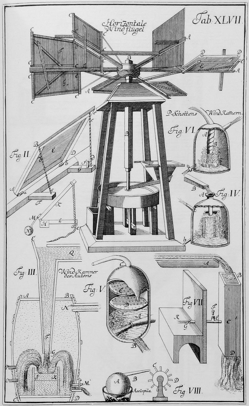
WIND POWER-ITS UTILIZATION AND VARIOUS APPLICATIONS.
A.D. 1724, October 26.- N° 471.
BRENT, JOHN.- "A wind engine or machine, which would be usefull in occasioning motion to all sorts of mill work, and for divers other uses and purposes, far exceeding all wind engines hitherto practised whose fanes move horizontally, and are so disposed as to work with the wind blowing from any point of the compass, without turning or altering the position of the said engine or house thereto belonging."
[No Specification enrolled. Letters Patent printed, 4d.]
A.D. 1738, June 24.- N° 561.via Windmill Hoppers
KAY, JOHN.- "An upright wind mill." This consists of two upright posts fixed in the ground and a cross beam tying them together at their heads. Betwixt the two posts is placed a moving shaft with center pins and sockets, in which shaft are placed eight arms horizontally, to which arms are hung four sails on moving frames, which receive the wind from any point, "and by means of the sails opening and shutting like a door and a brace or stay line on the back thereof are in full sail on one side the shaft and come up edgeways on the other." A cog wheel is at the bottom of the shaft. The force may be increased by adding "one or more teem of arms and sails," and by adding one arm the mill, in case of necessity, may be worked by horses.
[No Specification enrolled. Letters Patent printed, 4d.]
Upright Windmill for Raising Water, and for Draining Mines and Lands,
GEORGE THE SECOND, by the Grace of God, &c. To all to whom these presents shall come, greeting: Whereas Our trusty and welbeloved John Kay, of Bury, in Our county of Lancaster, engineer, has by his petition humbly represented unto Us, That he has by study, long application, and expence found out and invented a new engine or machine, which he calls an upright windmill, being to be moved cheifly by the wind, and is proper for raising of water, either for draining of lands or mines, or furnishing cities, towns, or gentlemen's seats with water, and applicable to many other purposes where great strength and force is required; which engine consists of two upright posts of timber strongly fixed in the ground, and a cross beam tying them together at the heads; in the middle betwixt the two posts is placed a moving shaft or runner with center pins and sockets both above and below for the shaft to turn on, in which shaft are placed eight arms or cross pieces, horizontally to which arms are hung four sails on moving frames, which sailes, when spread or braced, receive the wind without shifting the engine, let it blow from any point whatsoever, and by means of the sails opening and shutting like a door, and a brace or stay line on the back thereof, are in full sail on one side the-shaft, and come up edgeways on the other, till they have passed the center at the shaft and then come into full sail again, being so continued by their opening and shutting to receive the full force of the wind going forward, and not being impeded by it in the return, by means whereof the shaft or runner is moved round with great force and swiftness, which force may be increased at pleasure by adding one or more teer of arms and sails in the shaft one over another, according as the heighth thereof will admitt; at the foot of this shaft is fixed a cogg wheele or rundle that moves round with the same, and is applicable to and proper to perform all or most of the operations that are performed by other wheels that are moved either by wind or water, and has a further advantage that, by adding one arm to the shaft, the mill, in case of failing of the wind or other necessity, may be kept in operation by the strength or draught of horses: That the petitioner having often observed that amongst the various ways of raising water from a mine or deep pitt there are two that are performed by buckets, the one by two buckets that alternately descend and ascend by an engine moved by the strength of horses, the other is by a chain of buckets which are fastned to a chain and decend with the mouths downwards and come up full with the mouths upwards by means of a ragg wheel on which the chain is hung; that the first of these methods is attended with this inconvenience, that whenever the bucket is drawn up the horse must stand still till it is emptied, and then turn and draw the contrary way to bring up the other bucket, and so alternately during the working of the engine; the other method by a chain of buckets is attended with this inconvenience, that no method hath yet been found out in hanging the buckets to prevent there frequent being broke either by the rag wheel on which they run, on the chain on which they hung, by reason whereof the method of a chain of buckets is become of little use, the utility very seldom answering the expence: That the petitioner hath found out two inventions that remedy both these inconveniences, the one is by a rundel fixed on a spindle with a double crank, two wheels placed over the pit or mine from whence the water is to be drawn, two ropes or chains, one end of each rope or chain being fixed to the crank and the other end after several wrapings round the axis of the wheel over the pitt, in proportion to the depth, and being fastned thereto, and two buckets hung by ropes or chains at these two wheels, that shall go down and draw up from the pitt as the wheels are moved, then fixing the rundle to the cogg wheel (which may be to the cogg wheel of the upright mill or any other), as the cogg wheel is moved by the shaft the rundle shall be moved by the cogg wheel, and the ropes or chains shall pull round the wheels over the mine or pitt, which, by means of the cranks, shall lett down and wind up two buckets alternately, one going down empty and the other coming up filled with water, and, by means of a ketch or hook at the top, made to discharge themselves into a trough or receiver for that purposc, performing this operation by means of the cranks, and due proportioning the wheels and ropes which makes the buckets descend and ascend alternately, although the prime motion be continually progressive and without retrogradation; the other remedy for inconveniences attending a chain are to be hung six, eight, or more buckets, fastned thereto by an iron chain at the top, and a few links of a chain at one side about the middle of the bucket, and guarded by two wooden hangers on the sides of each bucket, by means whereof the buckets thus hung and guarded are prevented from ever getting under the main chain or being crushed thereby, and yett hang so loose that they yeild to the chain, and descend with the mouth downwards into the pit and ascend to the top filled with water by a constant rotation, which these buckets discharge on the surface into a trough for that purpose.
From Letters Patent-Rolls Chapel.
A.D. 1749, May 9.- N° 643. (* *)
LANGWORTHY, RICHARD.- "A machine which is be turned by the winds only, and of such contrivance and purchase that it will draw and extract with great ease any weight of water, metal, ore, or other weight whatsoever from pitts, quarries, and other great depths; that the said machine will also be very usefull to persons occupying windmills and stamping mills, and also on shipboard, for lifting great weights, and in many other cases will be of great emolument to the publick." This invention consists of an upright axis carrying vanes, which is mounted in suitable bearings in a kind of frame connected to a circular base, and is partially enclosed in a case, other vanes being also arranged on each side of the case. The last-mentioned vanes are for the purpose of turning the case into different positions when the wind shifts or alters, and so preserving the opening in the case in such a situation as to cause the wind to act in the required manner upon the vanes on the upright shaft, the other vanes being also adjustable by means of ropes or chains. These vanes, as well as the moveable case, are furnished with "wheels or trucks," which facilitate their being moved. On the lower part of the axis is a cog and spur wheel, for the purpose of driving the machinery requiring to be actuated.
[Printed, 6d. Drawing. See Rolls Chapel Reports, 6th Report, p. 123.]
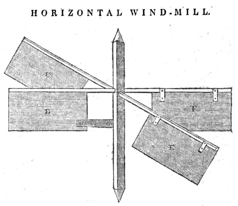
A new Horizontal Windmill &c.
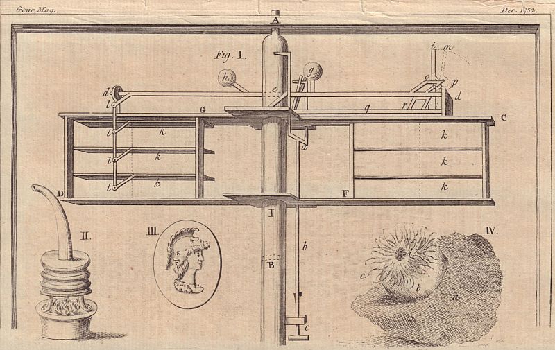
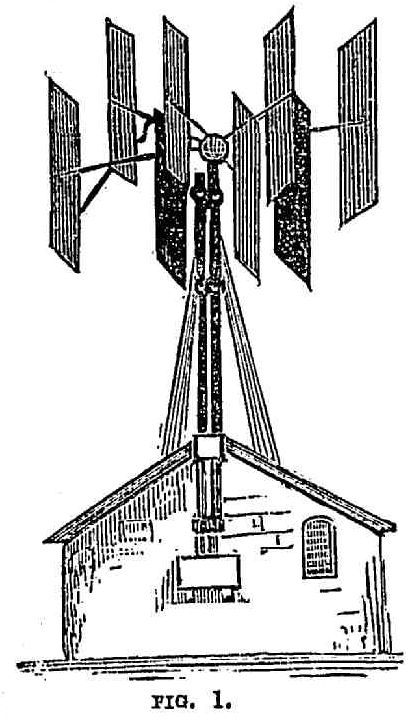
'Tis now near two years since I first thought of the enclosed scheme for an horizontal windmill, and should be oblig'd if you would insert it in your next Magazine, as the sails are here contrived to shift themselves to the wind in all directions, which is not so conveniently performed by the horizontal windmill described in one of your former Mags, nor in that mentioned in the Philosophical Transactions
Yours, &c. Νοv 14 1752.
FIG. I. A B is the axis perpendicular to the horizon, to which the arms C F and G D, together with those imagined to be at I and B, are fixed; each of these arms is divided into three partitions or valves as kkk &c. to the intent that boisterous winds should not have so great a power to damage the machine which would be the consequence if the whole surface C F or G D turn'd only on one axis. - The valves on one side of the axis open in contrary directions to those on the other side; those on the arm C F are supposed to be acted upon directly by the wind, and consequently must be depressed, while the wind (still blowing in the same direction) conspires to open the valves on the opposite arm G D, but acting upon them edgeways almost entirely loses its power on that space G D - Now in order that the valves on G D should be always elevated while those on C F are depressed, and vice versa, they have a communication with each other, by the iron rod d e d passing thro' the axis, and fix'd to the valves by the joints at l l &c. without which expedient the motion could not be duly regulated but sudden gusts of wind would elevate and depress the valves in an irregular manner.
The entire force of the wind upon this machine may be occasionally taken off, and that instantly (which must be confiderable advantage) by applying the hand at c, and pulling down the bar at a b, which forces the iron spring i o into the direction m p, by which means it is unhasped and disengaged from the bar d e d and consequently the valves on both sides of the axis may be elevated, and their edges be turned to the wind, by which the power of it will be taken off. The spring m p returns to its proper position at i o by thrusting the bar a b upwards. The leaden weights at g and b serve as counter balances that the weight of the valves k k &c. may not be any hindrance to their motion.
This machine wants no attendance except when out of repair, and revolves tho' the wind should veer about all the points of the compass in an hour, and consequently might be very serviceable in raising water for draining of fen land, working ventilators, &c
[A Patent has been granted several years for a horizontal windmill which regulates itself, and another for one to shift in all directions, by two or three methods a little different and not unlike the preceeding.]
Nos. 455, 456, 457. Eide Siade Johans, in a letter to Sec. R. S., suggests sending from time to time some of his 'lucubrations' to the Society. The specimens he forwarded occupy 12 pp. in German: they were translated, and were read on 10 May, 1758. Among the subjects treated we find these - Arca Noae; Solomon's Brazen Sea; The Two Pillars Jachin and Boaz; A. Horizontal Windmill; A New Invented Sluice or Dam. The writer does not seem to have been asked for further contributions.The unwritten suggestion is that his "lucubrations" were not very worthwhile.
From Thomas GilpinReply from Benjamin Franklin, July 10, 1769
Philadelphia May 16th. 1769.
Worthy Friend
By the brig Ketly Capt. Osborne I have sent you the model of a machine the result of a thought occuring to me some time ago which I have realised in the present form. It is that of an horizontal windmill applied to three pumps - this application as one of the most useful for raising water from lands, draining mines or pumping ships in distress at sea; but if the first movement be found effective it may be applied to all the various uses of other windmills, without the inconvenience of turning the house or frame to the wind. - I could mention some further objects that have occured to me on the subject but I daresay they will present themselves to you; when you have examined the model if you think the invention of sufficient importance I would thank you to have it shewn to the Society of Arts or made public in any way you may think it merits - the necessity of regulating and stopping the motion of the mill will no doubt occur to you; that part of it I have omitted at present from want of time, but it is very easy, nearly as much so as that of stopping a water mill and I shall have it fixed to another model I am preparing for the Philosophical Society here. Your sentiments on this invention at a leisure moment will be very gratifying and esteemed a particular favor by your friend
Thomas Gilpin.
p.s. I have an idea that this machine with some alterations would answer well in a current of water.
London July 10th. 1769.Further reply from B. Franklin, March 18, 1770 also discussing a number of other horizontal windmills
Sir, I received your favor per Capt. Osborne with the model of your machine for raising water. The manner in which you have applied a single crank for the working of three pumps wherein the whole force is applied to each & yet in such quick succession that there is no loss of time appears to me so extremely ingenious that I have scarce ever seen a new invention that gave me greater pleasure; and I am persuaded with you that it may be of great use in draining mines, quarries &c I intend to exhibit it to the Society of Arts when they meet in November next & believe it will meet with their approbation.
I am Sir your most obt, hbl Servt. B. Franklin.
To Thomas GilpinGilpin communicated with the Royal Society
London March 18. 1770
Sir
I receiv'd your Favour by the Hand of Mr. Abel James. An Accident happen'd to it in his Chest by the Breaking of a Bottle of some Liquid that obliterated part of it. I see however that it contains some good Remarks on the Advantages of Canals for internal Navigation in our Country, to which I heartily wish Success. What you tell me of the Practicability of navigating down Sasquehanah pl[eases] me extremely, as hitherto I had understood that to be impossible.
I wrote to you last Summer that I purpose to show your Machine to the Society of Arts. Since their Meeting I have till now been otherwise too busy to attend to such Things: but I lately pack'd it in its Box and sent it to their Store and am next Week to meet a Commitee of theirs to explain it to them. Many ingenious Men [have] seen it at my House and were much pleas'd with it. What they chiefly admire is not the Construction of the Sails but the Application of a single Crank to three separate Pumps.
I suppose you may not have had an Opportunity of knowing that the Manner of fixing your Sails, tho truly invented by you, has before been thought of by others. I did myself about 25 years ago make a little Model for W. Masters who had thoughts of executing it in large for Use. It was in all respects the same, except the Cord and Spring to each Sail which are in yours, and which I think may be a great Improvement; and except that I plac'd my Sails upright on their Ends; which I mention now for your Consideration whether the Force or Purchase is not thereby greater, no Part of it being so near the Center of Motion as when they lie on their Sides, and fall inwards; but of this I would not be positive. In a second Model I plac'd six Sails instead of four, for which there is good room when so plac'd upright, and I thought the Motion might thereby be more equable. A Friend of mine in Maryland, Mr. H Jones, to whom I had communicated this horizontal Windmill wrote a Paper about it which he printed, and with some Alterations erected a large one on his Land intending to apply it to the grinding of Corn; he nam'd it the Elephant from its suppos'd Strength: and when used in a Current of Water, which he also propos'd, would then have it call'd the Whale; but before his Elephant was finish'd a great Storm shatter'd it to Pieces, and he never repair'd it. My Son has now a Dr[awing?] of those Sails of mine done by Lewis Evans, in an 8vo manuscript Volume of Inventions collected by him. There is both a Plan of the Arms and Sails in their several Positions, and an upright View of them as applied to a travelling Carriage, which he fancied might be moved by them. My Son will readily shew it to you if you desire to see it.
Horizontal Windmills are not any where in general Use, except, as I have heard, in Poland. The Form there, is this. The Sails are all fix'd (in such a Position with regard to the Axis as the Radii of a Circle are to its Center) and upright Boards are fix'd all round them so as to throw the Wind to most Advantage against the Sails, let it come which way it will. A the Axis. a, b, c, d, e, f, g, h, the Sails fix'd to the Arms. 1, 2, 3, 4, 5, 6, 7, 8, the standing Boards to throw the Wind against the Sails.
I have seen but two horizontal Windmills in all my Travels. The first was at Rhode island, where the Sails were in the Form of the Foresail and Mainsail of a Sloop, four little Masts with such Sails were fix'd upright on the four Ends of a horizontal Cross; the Sails fill'd and jib'd successively as the Cross went round: It was over a Turner's Work Shop and the Application was to drive a large Lathe for turning heavy Mortars of Lignum Vitae. The other is now here at Knightsbridge near London, on the Top of a House for manufacturing painted Oil Cloths, and is used for grinding the Colours. The horizontal Wheel is in an octagon Tower with a Roof, but open all round the Sides; the Vanes are fix'd as in the Polish Mill; but to make it go, there are moveable Shutters, sufficient when properly plac'd to prevent the Wind acting on the coming Side of the Sails, and by leaving half the Tower open suffer it to act on the going side. This needs Attention and Care to shift the Shutters as the Wind changes and therefore seems not so good as the Polish Mill; nor is either of them so good as yours.
The Advantages of a Horizontal Windmill seem to me to be that the Building need not be so high as for the vertical one, therefore not so strong, therefore not so expensive; and it is always ready to receive the Wind from any Quarter, without the Trouble and Machinery necessary to bring the others about to face the Wind. But probably the others have the Advantage in some other respects which has continued them in general Use: their Force perhaps is greater.
I shall be glad to see your Contrivances for stopping or regulating its Motion. I dare say they are very ingenious. I once saw a very simple and as I thought it a very clever Method of regulating a Motion where the Power was applied unequally. It was this. From the Top of the upright Axis is hung two moveable Arms, with a Weight at the End of each. When the Axis began to turn, the Weights naturally receded farther from the Center rising higher at the same time; the greater the Force applied, the larger Circle they describ'd; and as the Force abated they sunk and describ'd smaller Circles in Proportion. By this Means the Excess of the Force applied was spent in raising the Balls and occasioning them to describe a greater Circle, whereby they pass'd thro' more Space in the same Time, instead of its occasioning more Revolutions of the Axis in the same Time: thus those Revolutions continued to be equable. And this applied to your Windmill, by lengthening the Axis upwards to give room for hanging the Weights might I imagine occasion an equality of Motion always regulating itself, tho' the Wind should be squally and unequal.
It must give you Pleasure to see the Contrivance of horizontal Wind mills become generally useful, and therefore you will excuse my mentioning a Manner of constructing them that almost every Farmer may execute without the help of any Workman, and which, or something like it, I have had an imperfect Account of as used in China.
Pumps in your ingenious Manner, tho' very proper for Mines, &c. when skilful Persons could readily be had to repair them, might neither suit the Purse nor be so easily kept in order by the common Countryman, and so the Use of them would not generally obtain for the Purpose of Watering Lands. Suppose then that in an open Field by the Side of a Brook or Pond, one of those Windmills is to be fix'd in the cheapest and easiest Manner to raise Water: A short Stake drove into the Ground might receive the lower Point of the Axis, its upper End might be supported by Cords made of Leatherwood Bark carried out on all Sides and fasten'd to Pins drove into the Earth: If the Arms are to be six it might be cut three square above and below where the Arms are applied to it, which might be of Saplins, the Buts a little flatted next to the Axis, and bound on; their small Ends being out every way to make the Circumference of the Circle. The Sails might be of Reed or Rush Mats extended on slight Frames and hung above and below by bits of Rope or Cord. An open Trough of plain Boards laid slanting up from the Water, and a Number of little square Boards nearly fitting that Trough, fix'd at proper Distances to a small Rope in the Manner of a Chain Pump, and kept going by the Motion of the Axis, might bring the Water continually from the lower End of the Trough to the upper, and there discharge it into the Channel made to carry it away. If one Set of these Vanes does not raise it high enough, as they are cheap and easily made a second or third, or any Number might be used in different Parts of the Field one taking the Water from the Level where the other leaves it. Any Man with Hands might mend such a Machine when out of order. And in the Season of the Year when they would not be wanted to Work, they might easily be taken to pieces, and the Parts carried in under Shelter to preserve them from the Weather. This Idea I submit to your Consideration, and am with much Esteem, Your most humble Servant
B Franklin
[A drawing appears here] A very bad Drawing, but may help a little to explain my Meaning.
Philadelphia Sepr. 28th 1770.I can only find a tiny fragment of the report in the Transactions of the American Philosophical Society
Gentlemen,
I had the honor to receive your favor by your Secretary Mr. Samuel Moore about two months past wherein you are pleased to expres your approbation of my improved hydraulic windmill which I am in hopes will be still further improved and turned to some useful purposes: give me leave to assure you that I am far from being so confident of my abilities as to be a creditor against the world for very important discoveries; but when I consider how much improvements have advanced step by step & how much is due to those who have made them before us I consider it the duty of every one to whom they occur to give his assistance upon the subject, and that to foster & encourage these is the object of your Institution.
Mr Thomas Gilpin has presented a model of a Horizontal Wind-mill; and writes to the Society as follows.
"That to obviate the difficulty of turning the house, or frame, of common wind-mills to the wind, he had contrived a model of a horizontal wind-mill, which he had ...
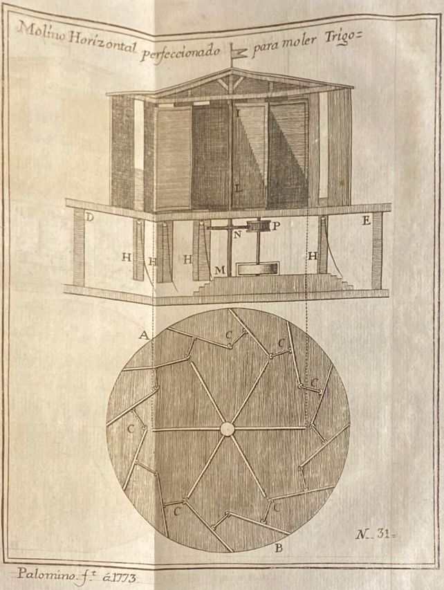
NUMERO XXXIApproximate translation:
MOLINO ORIZONTAL PERFECCIONADO PAR A MOLER TRIGO.
El plano del armazon A B de este molino no se diferencia esencialmente del que se publicó en el Numero 9. de esta Coleccion, mas que en que tiene mayor numero de tableros, y el aventador vertical dos alas mas. Los intervalos que quedan de tablero à tablero, y por entre los quales se introduce elayro à dar movimiento al aventador, se cierran quanto se quiere con las compuertas CCC que se suben, y baxan por medio de poleas, ò garruchas pequeñas ...
Number 31
Horizontal mill for grinding wheat.
The plane of the frame A B of this mill does not differ essentially from that which was published in this Collection Number 9, rather than in that it has a greater number of boards, and the vertical avenator two more sails. The remaining intervals of board to board, and between the sails it is introduced to give movement to the winder, they close while it is desired with the CCC gates that are raised, and they baxan by means of pulleys, ò small garruchas ...
A.D. 1776, April 1.- N° 1124.via Windmill Hoppers
McINTOSH, PETER.- "Horizontal windmill with a multiplying power upon a very different and much superior construction and broke and stopt in a very different manner from any mill that has ever yet been invented; the same mill to be likewise worked with cattle and the wind power to be put upon a watermill as occasion may require."
[No Specification enrolled.]
A.D. 1776 N° 1124.
Horizontal Windmill.
LETTERS PATENT to Peter McIntosh, of Burr Street, Wapping, in the County of Middlesex, Mariner, of his new invented "HORIZONTAL WINDMILL WITH A MULTIPLYING POWER, UPON A VERY DIFFERENT AND MUCH SUPERIOR CONSTRUCTION, AND BROKE AND STOPT IN A VERY DIFFERENT MANNER FROM ANY MILL THAT HAS EVER YET BEEN INVENTED; THE SAME MILL TO BE LIKEWISE WORKED WITH CATTLE, AND THE WIND POWER TO BE PUT UPON A WATERMILL, AS OCCASION MAY REQUIRE;" and that upon the whole the invention of the said windmill will be very useful and beneficial to society; to hold to him, his executors, administrators, and assigns, within England, Wales, the Town of Berwick-upon-Tweed, and all the Colonies and Plantations abroad, for the term of Fourteen Years pursuant to the Statute; with a clause to inroll the same within four calendar months from the date hereof. W. H. M. at Westminster, the 1st day of April, in the year above. By writ, &c.
Dated 1st April 1776.
(No Specification enrolled.)
so far back as 1748 machinery was established at Ashford in Derbyshire for sawing and polishing marble, the motive power being water; whilst in 1730, in Aberdeen, granite was sawn and polished by other than manual labour. The circular-saw was invented in 1777 by Samuel Miller, of Southampton, who employed a horizontal windmill to work itStory Of The Saw : Spear & Jackson Ltd. 1760-1960 adds the additional information that Miller's patent was No. 1152, registered on 5th Aug 1777, to be driven by the said horizontal windmill, but there's no evidence that any of the machine was ever built
an entirely new machine for more expeditiously sawing all kinds of wood, stone and ivory; and the saws are made of a circular figure
The most celebrated builder of horizontal windmills in England was Captain Stephen Hooper, who patented a design, from which were built a number of examples including at Battersea and Margate.
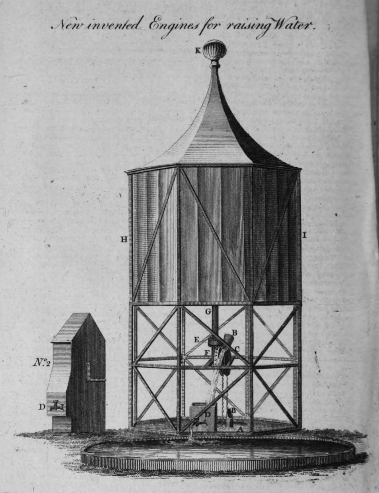
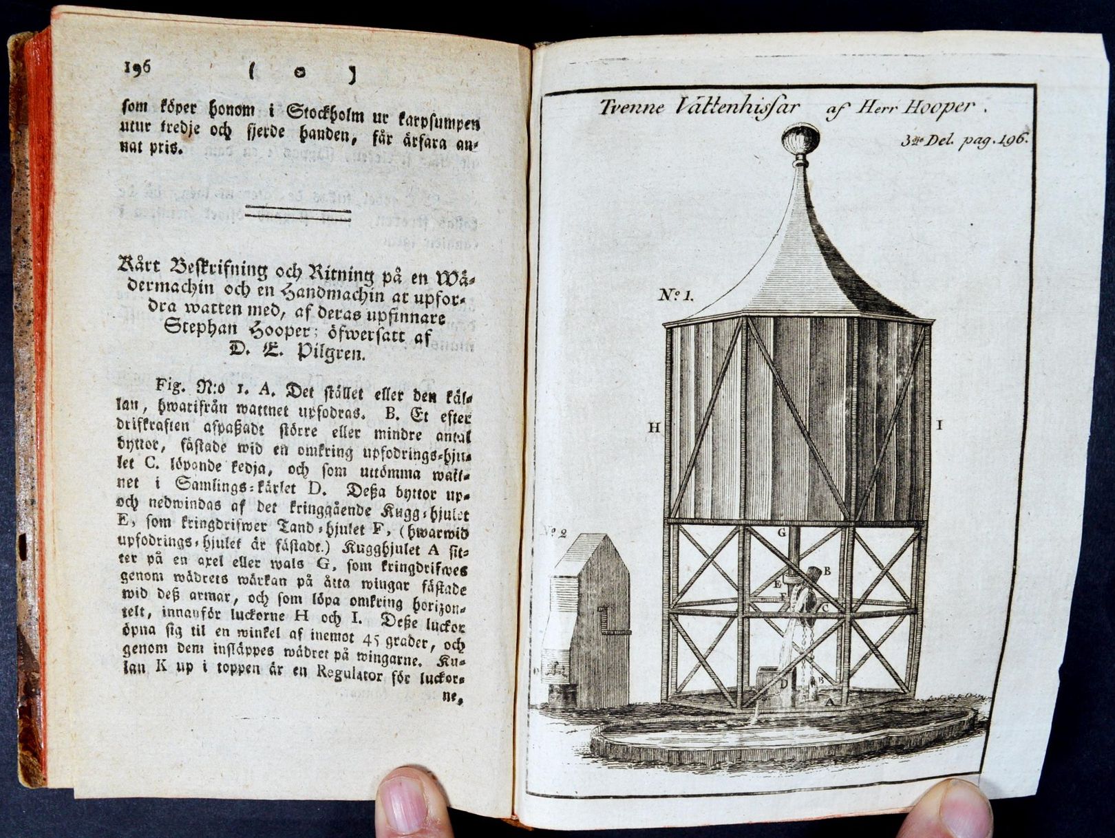
Hooper's patent (#1149, AD 1777) is for a device for raising water - which is of course an easier task than flour milling, since there is no need to keep a steady speed, water can be pumped at whatever speed is available, but to produce fine flour a constant speed is preferable. Whilst it's proved hard to track down the actual text of the patent, Hooper provided a publicity piece on the device, which was published in the London Magazine, October 1776, p465DESCRIPTION OF THE NEW INVENTED WIND AND HAND ENGINES FOR DRAWING WATER (With a curious Plate) BY THE INVENTOR AND PATENTEE, MR. STEPHEN HOOPER, OF MARGATE.The same information was published years later in Swedish: Ny Samling af Rön, Försök och Anmärkningar uti Hushållningen med mera, 1796 (via Facebook)A The place or well to raise the water from. B a number of buckets (fastened to an endless chain) which in turning over wheel C, empty themselves into a reservoir D. These buckets are put in motion by a swimming wheel E, working in F. The swimming wheel E is fastened to a shaft or arbor G, which is put in motion by the wind on eight flyers fastened to arms on arbor G, which run round in an horizontal direction, within the shutters H and I. These shutters open to an angle of about 45 degrees, by which means the wind is conveyed to the flyers. The ball K on the top is a regulator to the shutters, to shut or open them gradually, according to the strength of the wind. This engine is so contrived as to attend itself in every part, and will raise the water from wells, mines, &c. from 10 to 500 feet deep.
No. 2 is the hand-engine (the works for raising the water the same as in No. 1) put in motion by a winch.
Explanation of the various uses of these engines, and of the manner of working them.
Where a large quantity of water is required, and it is not convenient to fix a wind engine, the works may be carried forward by a horse, and will raise a double quantity in the same time to what is raised by the common method of bucket and rope; the well being covered over and a paul fixed to work in the wheel F, this will prevent the buckets running back, and takes off all danger from the person working or attending the same.
Where the water is at a distance from the house or place to which you want to raise it, it is brought to the spot by a tube or crane; this tube or crane will convey the water over a hill 30 feet high, and keep a continual stream, without the expence of cutting through the hill, &c.
Where a large body of water is raised in a reservoir to supply a town, &c. by fixing a tube (with a water-wheel in it) in a part of the reservoir through which the water must pass, will put this wheel in motion, from which the power is communicated to the outward part of the reservoir to assist the supplying the same with water.
This water-wheel is very useful in many manufactories, which are carried forward by water; it is put in motion by the current without any fall, its greatest power is when covered with the water, and it will work at any depth under water.
The wind part of this engine is the most useful in all manufactories, where a wind and water-mill may be required, as by the assistance of the regulator it requires no more attendance than the common water-mill, and may be fixed on the top of any building in the middle of a town, to work in the same, or at a small distance from it.
It is, likewise, so contrived, that it may be set on the top of a hill, and the power brought down into the valley, and communicated to any works at the distance of upwards of a quarter of a mile, and there will need no attendance at the top of the hill.
It is very useful in draining lands, being of equal power to any vertical mill, will carry forward the works without any loss of time (by taking in or setting sail) or risque of setting itself on fire.
This engine may be placed on the wing of any gentleman's house representing a turret, or where there is a turret, it may be fixed within the same to draw water, and for sundry uses in a family, as may be seen at George Medley's, Esq. at Buxstead-place in Sussex.
*** In justice to the inventor, who has favoured us with the plate, we beg leave to inform our readers, that they may be supplied with the engines, by applying to him at Margate, or to Mr. John Petit, Paradise-street, Rotherhithe, London.
One of the supposed selling points of Hooper's horizontal mill was its ability to self govern as the wind speed changed, though that turned out to not work in practice. Hooper however also worked to make vertical windmills more self governing, and had a patent for roller reefing sails granted: Patents for inventions. Abridgments of specifications, 1873[Text omitted, since it is printed in a very flowing script, and is in Swedish, and I cannot get OCR to handle it.
The text appears to have the same content as the English version, including the mention of George Medley at Buxted Place, and applying to Hooper in Margate or John Petit in London if you want your own instance built.]
A.D. 1789, October 29.- N° 1706.
HOOPER, STEPHEN.- "Machinery for regulating the power and motion of wind and other mills." One end of the sails "are fastened to cross lathes of the vane or sweep, the other to rollers to roll the sails upon when wanted." "In the centre of each end of the rollers are small gudgeons which work in centres in two rods extending lengthwise on each side of the length of the face of the vane." These rods are set in motion by other rods moved by necks working under and over a pinion which is connected with, and set in motion by means of, an endless string passing over a pulley within the mill. "These sails will attend themselves when the mill is at work by a weight connected with the extreme ends of the rods" at the sides of the vane, "so that when the weight by the velocity of the vanes or sweeps is forced out so as to overpower a counter weight fastened to a rope which works round a spiral wheel fixed on the cross shaft" to which the pulley is fixed, "the sails roll up in proportion to such velocity, and when the velocity abates the counterweight overpowers the weight on the vanes or sweeps and spreads the sails." The sails may also be constructed "extended lengthways on the vane," and "regulated on the same principle."
[Printed, 10d. Drawing. See Rolls Chapel Reports, 6th Report, p. 181.]
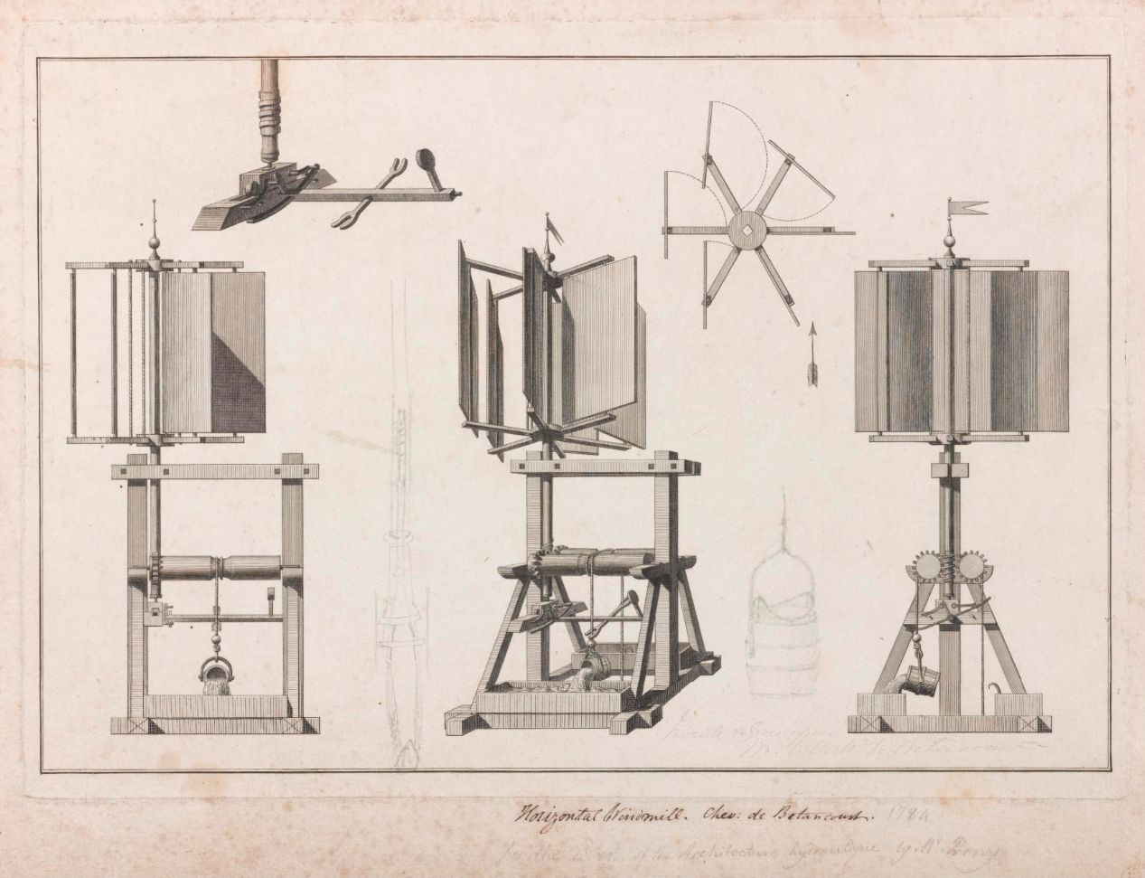
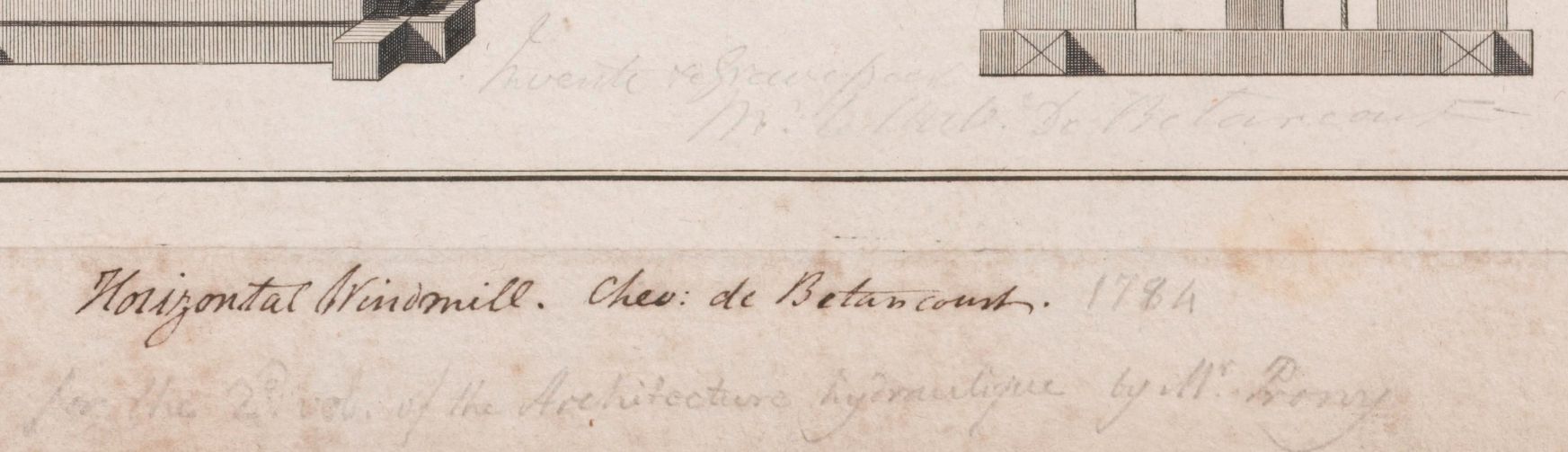
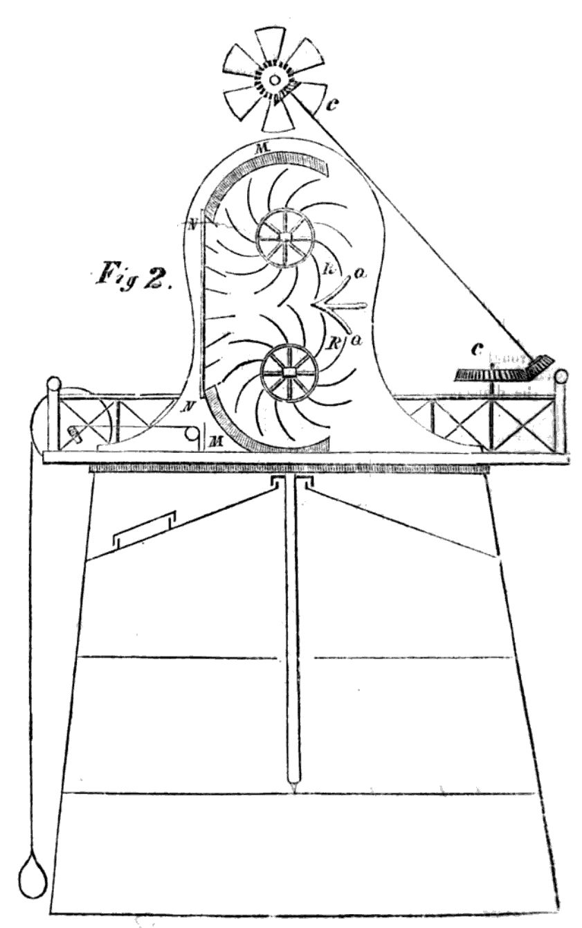
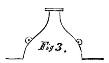
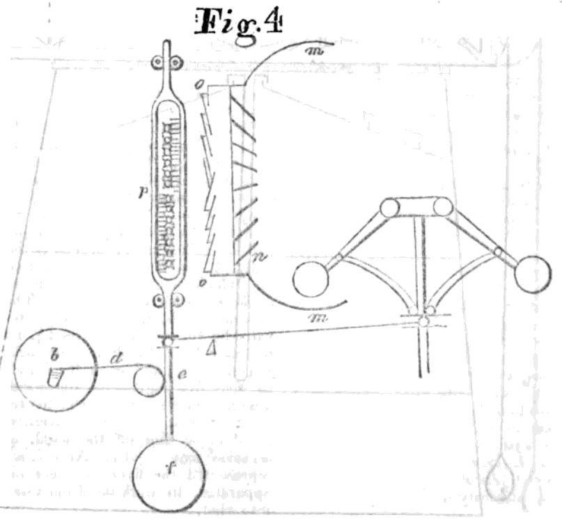
The bulk of the image is engraved, but there is a handwritten title to say "Horizontal windmill - Chev. de Betancourt.", which refers to the Chevalier (Knight) Augustine Betancourt, a Spanish engineer who travelled extensively through Europe. There are additional, pencil annotations (by other hands), which add the date 1784, and "for the 2nd vol. of the Architecture hydraulic by Mr. Prony". Whilst the image does not actually appear in printed copies of Prony's book Nouvelle Architecture Hydraulique, Contenant l'Art d'Elever l'Eau au Moyen de Differentes Machines &c., 1790 the style of the engraving matches those that do, so I think it correct to assume this was where it was prepared for.
There is additional pencil annotation in the engraved section, whose content is less clear, though the last word of this is "Betancourt", plus additional pencil drawings detailing the bucket, and possibly a water pump.
The windmill shown, via 3 side views, a plan view, and a detail view, has 6 sails, which rotate so that they present an open face to the wind, but close to present minimal profile on the upwind side of the rotation. The windmill raises a bucket of water, which empties out when it reaches the top, with the help of a hook that tips the bucket when appropriate. A mechanism triggered by a ball on the bucket rope causes the driving force to reverse direction, and thus return the empty bucket for its next fill. Since 2 water troughs, are show, the assumption is that there are 2 buckets employed, alternately rising full, and descending empty. Since Betancourt was an engineer, rather than simply an inventor, I think it probable that this drawing represents an actual example of a windmill that he encountered on his travels, rather than just a design that he made up himself.
A.D. 1792, June 14 .- N° 1890. (* *)
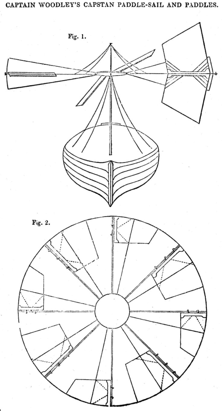
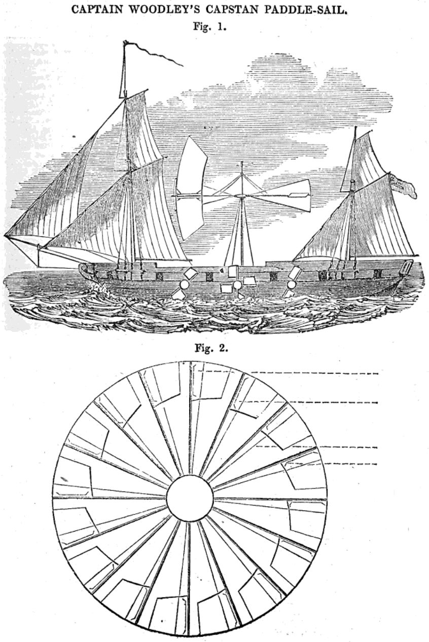
SILVESTER, GEORGE.- 1. A horizontal windmill consists of an upright shaft, with two sets of arms revolving upon it, and which carry between them long vertical vanes. By means of a crown wheel on the shaft gearing into a pinion on a spindle turning a wheel on the axis of each vane, the vane is caused to present to the wind its flat side when it is on one side of the main shaft, and its edge when it comes round to the other. To equalize the speed, a directing vane having a regulating weight attached to it keeps the machine in the most favourable position for the action of the wind, but when this is too strong, the upright shaft is partly turned round by the pressure of the wind upon the vane, and the action of the crown wheel on its top thus causes the mill vanes to be presented in a less favourable position for the action of the wind.
2. Feathering paddles. "The same motion may be likewise applied to floats of water wheels, or the working of common boats without oars;" the arms carrying the vanes or paddles would then turn vertically.
3. A horizontal windmill with sails or vanes turning on pivots connected by two endless chains, which move horizontally round wheels, are made with an unequal amount of surface on the two sides of the axis of each, so that the wind blows them open, and they are kept in an oblique direction towards it by cords, while the wheels are moved round.
[Printed, 10d. Drawing.]
Inventions and Improvements.
The science of Mechanics, is much in debted to the ingenuity of Mr. Robert Leslie of the city of Philadelphia. The following is handed to us as a list of a few of the inventions and improvements not including those on time-pieces, &c. which he has made during his residence here. Their merit will no doubt bring them soon into general life.
- A machine for threshing wheat, on a new plan.
- A horizontal tide-mill, to work with both tides.
- A boat to sail directly against the wind, or in any other direction.
- A horizontal wind-mill, so constructed, that the wind acts on both sides of the wheel at the same time.
An horizontal windmill is said to have been invented by an ingenious mechanic at Paterson, New-Jersey; the description appears to agree very nearly with that of a mill, for an improvement on which, an ingenious mechanic at Boston lately received a patent.
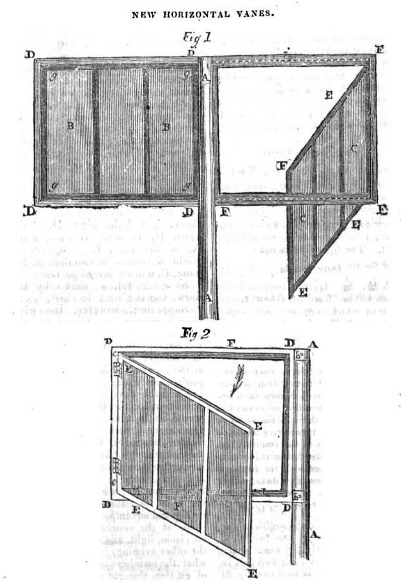
A.D. 1795, December 8 .- N° 2076.
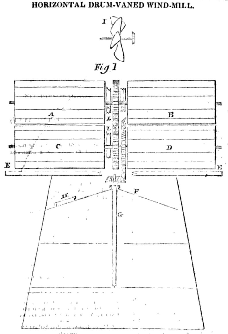
MAUNSELL, DANIEL.- Horizontal wind mill. This consists of two engines which may act together or separately. The first has four horizontal arms with sails made of thin boards or framework covered with canvass. These arms move on hinges or gudgeons "and being opened by the wind on the side which is intended to receive its direct impulse present perpendicular surfaces but are prevented from folding back by the boards which strike against four vertical bars." The wings above the arms or upper wings are prevented from closing too far by cords; the lower wings are at liberty. Weights are suspended by rods to the backs of all the wings and are nearly balanced thereby.
The second engine consists of twelve (the number may be varied) vertical boards which are fixed at equal distances round a cylinder and extend within about twelve inches of the circumferences of the top and bottom thereof. Wings whose number is equal to that of the boards are exactly fitted round the cylinder. "They are suspended on hinges or gudgeons and being opened by the wind strike with force against the vertical boards by which they allowed to open only so far as the open wing may form nearly a right angle with the closed wing " succeeding. "The motion of the engine may be stopped by cords fastened to three adjoining wings which are connected by one rope" passing into the interior of the mill.
A somewhat different modification of the first engine is also described.
[Printed, 8d. Drawing. See Repertory of Arts, vol. 7, p. 6.]
John Baptiste Aveilhe of Havre de Grace invented a horizontal windmill suitable for grinding corn, tobacco, and plaster; a model is on view at Federal Hill and for sale by Mr. Marche at 4 South Gay Street, BaltimoreThe National Intelligencer and Washington Advertiser, August 31, 1803
Patent Horizontal Wind-Mill.A similar advert published in South Carolina added raising water to the machine's uses: The Times, 13 Sep 1803 and The Times 10 Oct 1803
The subscriber offers to the gentlemen farmers and others of Maryland, and the other states, an invention, which for utility has not been exceeded by any piece of mechanism which this or perhaps the last century can boast of. It is a peculiarly, though simply, conftructed horizontal Wind-Mill, adapted to the grinding of all sorts of grain, and at the same time threshing out wheat and rice, fanning them and pounding the latter, powdering plaister of Paris, cutting tobacco, &c. Its aptitude to all those various and useful purposes, will be more easily and justly estimated by a view of the machine itself, than from any description that can be given here.
A model of this wind-mill can be viewed on Federal Hill, were it is kept for the conveniency of shewing it in operation, by applying to Mr. March, No. 4, south Gay street, by whom also the terms will be made known [f]or the model, only to erect a mill by, or for the patent right for a whole state or by
JOHN BAPITSTE AVEILHE,
The Inventor, Havre-de Grace.
Patent Horizontal Windmill.The windmill was not Aveilhe's only invention - he also received a patent for a Water Elevator - machine for raising water (perpetual motion), Oct 14 1802, #402X so his credentials as an inventor are instantly pretty suspect. (Other patents included a machine for boring holes in rock underwater, and a sugar mill). When creditors pursued him for bills run up in the construction of his house in Havre de Grace he had to auction all his property and it ended up passing to John Marche, who described himself as a broker, and advertised the auction, and was also his associate in demoing the windmill model.
The subscriber offers to the gentlemen farmers and others of South Carolina and the other states, an invention, which for utility has not been exceeded by any piece of mechanism which this or perhaps the last century can boast of. It is a peculiarly, tho' simply, constructed Horizontal Wind Mill, adapted to the grinding of all sorts of grain, and at the same time threshing out wheat and rice, fanning them and pounding the latter, powdering plaister of Paris, cutting tobacco, raise water, &c. Its aptitude to all those various and useful purposes, will be more easily and justly estimated by a view of the machine itself, than from any description that can be given here.
A model of this Wind Mill can be viewed for the convenience of shewing it in operation, by applying to the subscriber, or Mr. Peter Delportes, No. 179 Meeting-street, in this city, by whom also the terms will be made known for the model, only to erect a mill by, or for the patent right for whole state, by
John Baptifte Aveilhe, inventor.
September 12.
Sale by Auction.
On SATURDAY, The 30th of November, inst. at 12 o'cloct at noon, (by virtue of a deed of trust for that purpose, executed by John Baptiste Aveithe, and his wife, late of Haore-de-Grace,) I will offer for sale, by public auction,
Five Lots of Ground
In the said town, or such of them as he was entitled unto, fronting 300 feet on Union-street, and extending back 200 feet, to Freedom-ally; distinguished on the plat of the town, by the Nos. 60, 66, 73, 80 and 87: together with the Brick Dwelling-house and all other improvements thereon made.
The Lots are in fee-simple, and will be sold, either together or separately, upon' the premises; and the terms and conditions of the sale will be then published.
JOHN MARCHE, Trustee. Havre-de-Grace, Nov. 2.
A.D. 1806, October 7.- N° 2974.
SAMPSON, WILLIAM.- Windmills. The first part relates to horizontal engines. Two or more opposite arms are fastened transversely to the top of an upright shaft; each arm is turned up at the further end to form a crutch or hollow semicircular socket. A shaft of iron having a fan or sails at each extremity is placed horizontally on the crutches of each pair of opposite arms, and is provided with three stays; the fans or sails at the opposite extremities are in planes perpendicular to each other. Two of the stays are to prevent the axis from moving more than a fourth of a circle in turning on its crutches. This is done by each butting alternately on the transverse arms. The third stay is for the purpose of suspending the action of the shaft. By these means the sail moving with the wind is made to assume a vertical, and the opposite sail a horizontal position.
The second part relates to a mode of clothing and unclothing the sails of any windmill by means of small sails fixed on a small shaft contained within the main shaft hollowed out for the purpose. The cloths of the mill sails are fastened to the transverse parts of T-shaped pieces of timber, the shafts of which are worked backwards or forwards by chains or rackets and a wheel on the small shaft. This small shaft is made to revolve with different velocities by a brake regulated by hand or centrifugal balls.
[Printed, 6d. Drawing. See Rolls Chapel Reports, 7th Report, p. 194.]
HIGHLAND SOCIETY OF SCOTLAND.
A General Meeting of this SOCIETY was held in the Hall of the Royal College of Physicians here, on Monday last, ...
It appeared from the Secretary's statement, and a Report of the Standing Committee of the Society, on Machinery and Manufactures, that several Inventions or Improvements in Machinery had been under the consideration of the Directors; among others, a Claim for a Premium by Dugald Maclachlan, at Auchleven, near Bunaw, Argyllshire, for erecting a Mill for Carding, Teasing, and Spinning Wool, at a considerable expence. A Drawing and Description of Coupled Harrows, by Walter Samuel, at Niddry, Linlithgowshire, and the model of a Horizontal windmill, by Mr Henry Meikle, at Broadlaw, in the same county. The Model of a Reaping Machine, constructed by Mr Smith, of Deanstown-works, Perthshire, and presented by him to the Society, attracted much attention. The principle of this machine, and its mode of operating, were explained by Mr W. Campbell, and Mr Jeffrey of Allerbeck, Members of the Committee, the former of whom had repeatedly seen the machine itself in actual operation. The Meeting, on the motion of Mr Graham Dalyell, resolved, That it is proper in this Society, at all times, to promote and encourage ingenious and useful inventions, especially when connected with the objects of the Society, and that Mr Smith's perseverance in endeavouring to construct a machine so important to agriculture, and the degree of success which has already attended his exertions, entitles him to the thanks and patronage of this Society, and the Public. The Meeting farther recommended to its Members, to witness a trial of this machine next harvest, when completed upon the improved and extended plan, described by Mr Smith to the Directors.
ANOTHER WIND MACHINE, Furnishing immense Powers.The whole device looks rather impractical and I suspect was never built. The collection of 100 designs also includes a vertical windmill with counter rotating sails, which claims to deliver double power, but which looks similarly impractical.
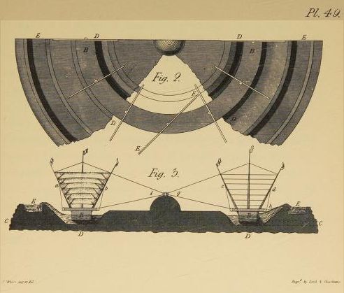
THIS is the last of those conceptions I shall now bring forward, for making more than a common use of the WIND as a first-mover of Machinery. Horizontal windmills are well known; and this is a horizontal windmill — yet not like those already in use: for, here, the sails, very large and numerous, are placed on a boat in the form of a ring, which thus moves through the water without any other resistance than that arising from the asperities of it's surface.
In Plate 49, fig. 3, B B is a section of the Vessel, placed in a circular canal D, into which the lower water flows through proper arches (C C) in the banks. The vessel is rigged with several narrow horizontal sails, stretched on ropes between the oblique masts a b, c d; and so placed, that the sails (being a little wider than the interval between the ropes) can open in one direction, but not in the other; and they are shewn open at c d, and shut at a b, in the figure. This, therefore, is a mill, that takes all winds; and although it's uses might be various, we shall finish it's description as adapted to raise water by the centrifugal force. As before hinted, the canal D D is circular; and has a bank, sloping outward, with a canal (E) on it's top. When, therefore, the wind blows, the ring boat B (held to the centre by the ropes f g) revolves around it; and by one or more water drags (h) which it carries, collects the water on and up the bank, and finally drives it into the canal E, from which it flows in any destined direction. If for draining watery lands, it will be done rapidly; if for irrigating, it will be done abundantly: if, in fine, for driving any mill with the water thus raised, the machinery will be very efficient, as working with ten or twenty times as much sail, as any other windmill can carry. I add, merely on this occasion, that the sails here mentioned, might be placed obliquely, instead of straight across the ring vessel; (see the plan in fig. 2 of this Plate at E F) from which disposition, nearly all the advantages of the vertical mill might be transferred to the horizontal; and with this remark I leave the present interesting subject to the studious and candid reader.
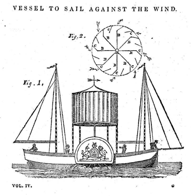
VESSEL TO SAIL AGAINST THE WIND.
SIR,-I send you the plan of a Vessel to sail against the Wind, or, as the sailors term it, "in the wind's eye."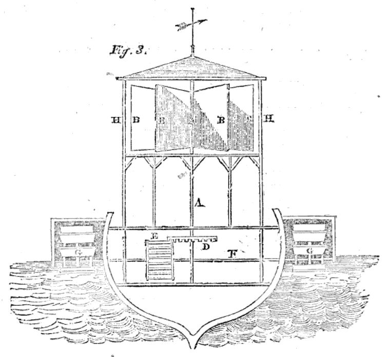
I am, Sir, Your obedient servant, ROBINSON CRUSOE.
Description.
Fig. 1 is a view of the vessel complete.
Fig. 2 is a ground-plan of a wind-box.
A is a vertical shaft, which supports the arms, BBBBBBB; to these arms are attached vanes or sails, which, when acted upon by the wind, cause the shaft, A, to revolve. CCCC are wind-guides, or thin boards placed vertically in the whole circumference of the wind-box, which allow the wind to pass between them in the direction marked by the arrows. By this arrangement, from whatever point of the compass the wind may blow, the vanes or sails must turn one way; and, by an inspection of figure 3, it will be seen that the vessel will proceed in any direction in which her head may be placed.
Fig. 3 is a transverse section of the vessel in midships. A, the shaft. BBB, &c. the vanes or sails. (The wind-guides are not shown in this figure, as they would obscure the vanes.) D, a cog-wheel, which, working in the trundle, E, turning the shaft, F, and giving motion to the paddle-wheels, GG, propels the vessel. HH, the wind-box.
The first reply to this query is to mention the Battersea horizontal mill - hardly a useful reply, since it's clear that this is on a totally different scale than was being enquired about Mechanics Magazine, no. 109, Sept 24, 1825No 145 Wind-lathe
Sir - Having a workshop in the centre of a town, and in which I have a Lathe, which I wish to work by sails, on the principle of a windmill, but which must have the sails in a horizontal position, I wish to know how this would act; and will thank any of the contributors and Correspondents to your Magazine to favour me, through its medium, with a plan or description of this sort of wind-engine. I should wish the description to state how many arms there should be, and whether every other arm should dip or not, to catch the wind better. Any other information on the subject either derived from personal experience, or from books, or otherwise, will be very acceptable, as I never saw a movement of this description.
I remain Sir, Your very obedient servant E.B. Cabinet maker. Skipton, near Craven.
ANSWERS TO INQUIRIES.The first reply to actually address the query is supplied with very primitive drawings. Mechanics Magazine, no 113, October 22, 1825
NO. 145 .- WIND-LATHE.
Sir.- If your Correspondent, "E. B." is in the habit of visiting London, he may see a beautiful horizontal mill at Battersca. The sails consist of a large wheel, exactly like an undershot waterwheel, only much longer in the direction of the axis; this is placed with its axis vertical, and is provided with a semi-cylindrical case, revolving about the same axis, the diameter of which semi-cylinder is adjusted to coincide with the direction of the wind. Thus one-half the sails are exposed to the wind, and one-half sheltered, and a rotatory motion is produced.
I am, Sir, Yours respectfully, F. O. M.
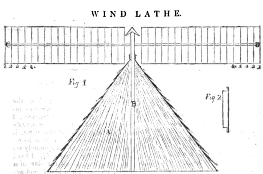
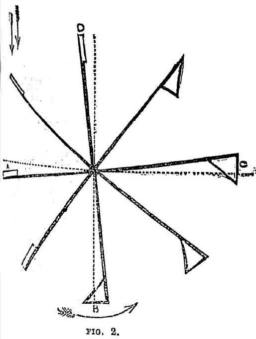
WIND-LATHENote that the wind direction in Fig 3 is incorrect - it should be reversed. Essentially the same design as above was repeated, uncredited, by a correspondent who signed themselves Liver, in English Mechanic and World of Science, June 14, 1867, where again it is in response to a question about using a windmill to work a lathe. That version has correctly reversed the wind direction. Whilst not specifically referencing the ongoing thread, the next issue has an even more primitive drawing. Mechanics Magazine, no 114, October 29, 1825
Sir, - You will doubtless have descriptions of the best method of constructing this apparatus (see Inquiry, No. 145, page 350, vol. iv.) from more able hands, but the following remarks and deseription of the 'arms' may be serviceable. I think that four arms are sufficient, or superior to a greater number, for the wind cannot act on more than one at once, and, with four, before the wind has lost its full action on one, another will be coming into play. The arms can be made of any length or depth, according to the power required. I will attempt to sketch a pair of arms, or section of the top of the shaft, upon what I conceive to be a good principle.- (See the prefixed figure).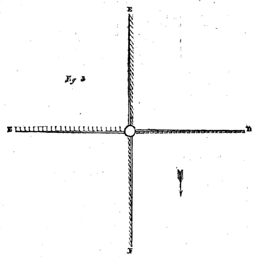
Description.
A (fig. 1) is the top of the house.
B, the perpendicular shaft.
C and D, two wings or arms.
1, 2, 3, 4, &c. are narrow slips of board (see fig.2) similar to a Venetian blind, and falling together towards the shaft B.
The wing, C, is represented open.
The wing, D, closed, as when the wind is acting upon it. [From want of shading, this is not so well represented in the drawing as it should have been.- EDIT.]
Fig. 3 is a horizontal section of the shaft and wings. The wind blowing from F to E will close the wing F, act fully on the wing D, be neuter on the wing E, and have a free passage through the wing C.
If you should find the present rough sketch worthy of insertion, I will, if it be necessary, give further particulars at some future time.
Believe me, Sir, Yours respectfully, R__ H__.
P.S. The ahove has one peculiar advantage over the Battersea Mill, mentioned by a Correspondent in No. 109, namely, that it will serve for all points of the wind without any shifting: the shifting apparatus, and the trouble of shifting upon every change of the wind, are both dispensed with. The same property belongs to the American Mill, described by Clio, at page 212, vol.iv. of which the above sketch is only a variation: it is merely substituting a self-acting vane for the sails.
Picking up on the mention of Battersea mill, a friend of Captain Hooper's contributes an interesting, but not relevant to the thread, memoir of the inventor. The full text of this memoir can be found on the page about the Battersea Horizontal Windmill. Mechanics Magazine, no 117, November 19, 1825Sir, - Perhaps the following simple method of constructing a Horizontal Wind-Mill, may be acceptable to some of your numerous mechanical readers.
I am, Sir, yours, &c. T. T.
Description.
AB is an upright shaft, into which the four arms are inserted at right angles. The sails, CDEF, are formed of some light substance (in my model of pasteboard), and fixed to the arms by joints, so as swing freely one way, but are prevented swinging in the opposite direction by a stop placed behind each, as at G. Now, when the wind blows upon the sails, in any direction, suppose upon DF, the sail, F, being prevented from swinging upon its joints by the stop in the back-part of it, the wind will, of course, drive it forward; while the sail D, whose stop is on the opposite side to that of F, will rise, and permit the wind to pass freely under it, and the desired motion will be produced. Perhaps six or more arms, placed so as the wind might act upon as many as possible at the same time, would, in this case, be preferable to four.
It need scarcely be observed, that the greater the extension of the arms from the vertical shaft, the greater the power of the machine.
BATTERSEA MILL - MEMOIR OF THE INVENTOR, CAPTAIN STEPHEN HOOPER.The thread continues with a recollection of an attempt to power a paddlebaot with a horizontal windmill. The author says it failed, with the boat rotating in the water, which he believes can be solved, if only he had more free time. Mechanics Magazine, no. 118, November 26, 1825
Sir, - In Number 109, page 399, of your interesting Miscellany, a Correspondent has called the attention of your readers to the beautiful Horizontal Mill at Battersea. This circumstance has revived in my mind some pleasing recollections of the years that are past, when I numbered the inventor of that ingenious piece of mechanism among my most valued and excellent friends; and it has also suggested the idea, that a short memorial of him and some of his inventions might not be unacceptable to the readers of the Mechanics' Magazine. ...
A correspondent claims to have constructed such a machine to drive a 2 horse threshing machine. Mechanics Magazine, no 129, February 11, 1826Sir, - In the 114th Number of your valuable Miscellany, there is a drawing and description of a Horizontal Windmill by T.T., who probably thinks that the idea is a new one, which, however, is not the case; for, about nine years ago, I made a similar one on a small scale, with this difference, that I fixed a large flat piece on the top of the upright shaft, on which the arms lay, one crossing over the other at right angles, and secured to it with collars, in which they might revolve freely in a vertical direction. The vanes, instead of being attached to the arms with hinges, as T.T.'s, were firmly secured at right angles to each other; or, in other words, if the vane at one end of each of the arms hung perpendicularly downwards, those at the opposite ends would be horizontal, and vice versa. It is therefore evident, that whichever vane catches the wind, it is forced downwards towards the perpendicular, and in that position recedes, and is succeeded by the next; while that at the opposite end of the arm, as before-mentioned, is by the same action borne upwards towards the horizontal, thereby offering but a trifling resistance in advancing to that point where it preponderates, catches the wind, and assumes the perpendicular in its turn.
I applied it to a boat with paddlewheels, with a view of propelling it against the wind — an object that I have no reason to think unattainable, although it failed with me at that time, owing to the horizontal revolution of the sails giving a tendency to the vessel to wheel round in the water in the same direction; I therefore gave up the experiment, with the intention of attempting it at some future time in another form, by making use of two sets of sails, one over the other, made to revolve contrariwise, by which means the tendency given to the vessel to wheel about by one set, would be neutralized by the contrary tendency given to it by the other. This, though I still think it practicable, is mere theory, as my other avocations have not afforded me leisure sufficient to bring my intended experiment to the test, necessary to form an accurate judgment of its claim to further consideration and improvement.
I am, Sir, Your very humble servant, S_____, L__q__p__d-street.
An earlier correspondent provides more info, but admits that this is largely theoretical. Mechanics Magazine, no 131, Feb 25, 1826Sir, - In Number 113 of your valuable Publication, there is a description given of a Wind-Lathe, or what I should rather call a Horizontal Windmill, by a person signing himself "R. H." Conceiving that such a power might with advantage be applied to actuate a two-horse threshing machine, I constructed a model on R. H.'s principle, and, as far as that goes, find it answer my fullest expectations; but knowing how defective those are in general, when compared with the actual engine, and that many have been led into serious losses by supposing that the machine, in its full size, will work equal to the model, I have deferred any farther proceedings until some more particular description shall be afforded by R. H., which in the article he has promised to do. R. H. will confer a favour, if he will give a more accurate description of the several parts of the machine; viz. what should be the length and depth of the arms or wings; the breadth of the narrow strips of board to act in the manner of a Venetian blind, the height the arms or wings should be elevated above the ground, so as to obtain a sufficient power from the wind; the whole calculated to work a threashing-machine of three or four horse power, with fanners, &c. attached to it for cleaning the corn.
The above being inserted in your next publication, will oblige a constant subscriber.
N.W.G.
Mechanics Magazine, no. 142, May 13, 1826Sir, - I fear that I shall not be able to answer satisfactorily the questions proposed by N.W.G., in a late Number, but I feel it necessary to say a few words on the subject, in explanation of my promise to give further information.
The whole of my knowledge - if it can be said to be knowledge - of the good or bad properties of the Horizontal Windmill, which I attempted to describe in No. 113, depends upon theory; I have never seen any thing of the kind put in practice. It appeared to me to be an improvement on the plan previously described by Clio, in No. 98; and all that I could have then said, or can now say, more than is stated in my first communication, would be to point out wherein this improvement consisted. If the principle be good, of which I have no doubt myself, and which the model made by N. W. G. seems to prove, the minor matters, as to length of arms, height, &c. may be left to the judgment of the builder, to be regulated according to the quantity of work required to be done, and the situation in which the mill or lathe may be erected. On the top of a hill, or on an open plain, the elevation of the arms need not be great; but, in partially confined situations, the building must, of course, be high. In this respect it would be like the common windmill.
I am fond of experiment, and had I the means, which I have not, I would make a good-sized model, in order to convince myself of the effect produced by the horizontal arms. Were I to have the direction of putting up a mill on this principle, to do a given quantity of work, I should calculate as near as I could as to the surface necessary to each arm, by a comparison with mills on the old principle, but at the same time making the arms in such a manner that I could easily either lengthen or shorten them. The necessary extent of surface may be thus obtained without any great trouble or expense. I know of no other way: the wind seems too variable in its effective power to allow of any thing like accurate calculation to be built upon it. It is necessary that the arm should have sufficient surface to do the required work with the aid of a moderate wind; and it is necessary also that this surface be easily contractible when the wind is more fresh. This I should think may be done by some easy means of fastening (either open or closed will do) any number that may be required of the windboards. The breadth of the wind-boards is but of little importance, and may be made to suit the taste or the convenience of any one who may adopt the plan. The height of the mill should be regulated by the situation, the favourable or unfavourable circumstances attending which may be easily ascertained.
The above are not answers to the questions of N. W. G.; they are merely hints on which he or others may perhaps improve.
I should be happy in being favoured with N. W. G.'s address. I trust that I shall not offend. If he will leave his address with the Editor of the Mechanics' Magazine, directed to R. H., he will oblige me. I shall be in London during the coming Spring, and should N. W. G. live in or near, and have no objection, I should feel happy in having a sight of his "model."
I am Sir, Your Obediant Servant, R__ H__.
MODEL OF A WINDMILL WANTED.
Sir, - I have a patent corn-mill (one strong man power), which I much wish to work on R. H.'s plan (No. 113, vol. v.); but his is objectionable, on account of noise, my mill being in a private house: I also wish to be able to shift the wings or arms, leaving only the perpendicular shaft standing. Now, I would willingly present a guinea to any mechanic who would produce me a model which shall answer my purpose. The mill is now in a loft in the roof, with R. H.'s perpendicular shaft B attached to it, but my ingenuity can get no further.
I remain, Sir, Yours respectfully, W. W. H.
Although the name of the correspondent is partially obscured, this may be Henry Ottley, whose work on algebra (which the cryptic "late 1 and 2 make 3" possibly alludes to) features in Mechanics Magazine, no. 224, December 8. 1827, where Ottley is described as "our intelligent correspondent".Sir, - I beg leave to offer you for insertion, the description of a new kind of horizontal vanes, to work mills, &c. of my own invention.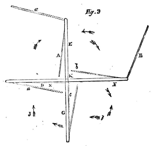
They are very simple, and will answer, I have no doubt, exceedingly well. The following is the
Description.
A A, fig. 1, is a perpendicular shaft, having fixed to it four frames (two of which only are here represented) D D D D, and F F F F, to the exterior ridges of which are fastened, on a hinge, other frames, E E E E, and g g g g, which open like doors, only in one direction, being prevented, by the groove shewn by the dotted lines, from turning the other way (see fig. 3); this frame, E E E E, is to be covered with tarpauling, such as is used for the sails of wind-mills. Fig. 2, is a more minute delineation of the frame, E E E E, is the interior frame of wood, moving on the hinge e e, as before said, and is supposed to be open towards the spectator; it is prevented from opening the other way by the projecting groove, i i i.
A slight inspection of fig. 3, will sufficiently shew how the wind acts on these vanes. When it blows in the direction shewn by the dart, I, the moveable wing, B, of the frame, F, is wide open, being blown so by the wind, and the wing, D, of the vane, H, is perfectly shut, while A, of the vane, E, is open in a slight degree, as is also that of the vane, C, when it is evident the whole must go round, as shewn by the darts, together with the shaft, k.
Supposing, however, the wind should change, as shewn by the dotted dart, 4, the wing, C, would immediately shut, as shewn by c, - D would open in a slight degree, as shewn by a, and A, would be wide open, as shewn by the dotted lines, a, &c. and the machine would continue to go round in the same direction. It would be the same, let the wind come from any quarter.
The two bars, F F, (fig. 2,) are to pass through the shaft, A A, and be further secured by pins, h h.
I am, &c. HENRY O****Y,
Late 1 and 2 make 3. September 18th, 1826.
HORIZONTAL, DRUM-VANED WIND-MILL.Sir, - I am at a loss what name to give to the inclosed sketch; however, for the sake of distinction, I shall call it a Horizontal Drum-Vaned Windmill.
A B, and C D, fig. 1, represent a front view of four wind drums; on the middle of the shafts, at L L, two tooth wheels unite their power.
The bevil wheel in the lower shaft works into the crown wheel on the vertical shaft, A, which passes through the fixed roof, at F, to convey motion to the working apparatus in the mills. Upon this shaft, at F, is a running bow, to prevent wet entering the mill. At H is a hatchway, to ascend outside the roof. The flyers, at I, are supported by two metal bridges, fig. 3, which arebolted down upon the two headstocks, K K, of the upper drum shaft. The frame work, E E, which supports the wind drums, is screwed down upon the moving part, which is constructed the same as other turret-built mills which are wrought into wind by flyers. Fig. 2, is an end view of the drum vanes; the diameter of each is ten feet, which will admit the breadth of the vanies, on each drum, to be four feet; their length may be extended at pleasure, by making provision in the building, &c. The vanes are curved that they may quit the wind backwards with more ease by their centrifugal force; at M M, the vanes are screened from the wind. The space from N to N, in front of the mill drums, contains an opening, the partitions of which are so adjusted, as to direct the wind to strike square upon the vane. These partitions I shall call the directors. In front of and close against these directors, are the blinds, o o, (see fig. 4,) which are opened or shut by the motion of the rack, p p, whose teeth lath into small pinions fixed upon the axis of the blind; the rack being moved by the motion of the governor. The rack and blinds in the drawing are placed alongside each other, I could not shew them connected.
One half of the blinds at o o, shut upwards, and the other half shut downwards. This requires the rack to be toothed half way on one side, and the other half on the contrary side, which opens the blinds parallel with the directors, and facilitates the entrance of the wind. The intent of the directors is, that whether the blinds are more or less opened by the regulating motion of the governor, the wind may continue to strike upon the vanes in the same direction.
At Q.Q, fig.2, is the intercepting part curved to the periphery, of both drum vanes, which prevents the wind escaping the passing vanes, R R. till the succeeding ones come in contact; thus obtaining its whole force on the wind drum. Without this precaution the wind would escape in a current stream betwixt the vanes as they were approaching to and receding from each other, in their revolutions.
Fig. 4, represents the blinds shut, which are to open and set the mill a going. The chain, d, which coils round the pully b, must be pulled down, and the weight, G, (see fig. 5) hung thereon. To prevent its return, the chain, d, at the same time, will be coiled round the axis of the pully, b, and the weight, f, raised up, which slackens the chain, e, connected with the rack, p. The governor balls, that were kept elevated by the weight, f, (see fig. 4,) will now descend and raise the rack, p, (see fig. 5,) and open the blinds to give free ingress to the wind. The rack now remains under the regulating motion of the governor, to admit or shut off the wind, as occasion may require. At o o, are represented the flyers and geering apparatus, to work the drum vanes into wind.I am of opinion, that horizontal mills, with one mill drum only, labour under great disadvantages. In the first place, a broad vane is useless; the drum being cased round with blinds, they are all opened to the same angle to admit the wind, and it cannot be directed to cover the surface of a broad vane, as the wind will be continually screened from a great part next the drum by each succeeding vane. Secondly, a great part of the force of the wind will be lost, by being exerted against the blinds while passing round with the vanes. Thirdly, the want of a ready egress for the wind backwards, will greatly retard the speed, and diminish the power of the third drum.
But, by causing the wind to pass betwixt two drums, its whole force is confined to act upon the vanes, which may be of any desired breadth, and, at the same time, accommodated with a ready passage for the wind to escape backwards.
And I am bold to assert, that a mill, erected upon this principle, would be able to compete with any vertical sailed wind-mill in the kingdom; allowing the drum vanes an advantage in their area, equal to the extra leverage of the others.
I am, Sir, Your humble Servant, A YORKSHIRE MILLER. Barnsley.
Construction of fountains for gardens.
...
The water may be raised to the basin or cistern so placed, by forcing-pumps worked by men, horses, wind, water, or steam; or by that very ingenious machine, the hydraulic ram, which we have before noticed (Vol. V. p. 594.) as being in use at Bury Hill; and which has lately been put up, in various parts of the country, for this purpose, by Mr. Rowley. However, the mode which we would recommend, as most directly applicable where there is no natural power, is that of having a small steam-engine, say of two-horse power, which might be placed in the lower part of the tower containing the cistern, or in any convenient situation near the well, pond, or other source of supply, and set to work once or twice a week, as occasion might require. A horizontal windmill, so disguised in the tower as not to be an offensive object, would, in all elevated situations, as we have elsewhere observed (Encyc. of Cottage Architecture, § 1256.), be the cheapest and best that could be employed; because it would require little or no attention, and might be left to itself, to work or stand still, according to the wind. The construction of such a windmill is exceedingly simple, and no man that we know is more fit to carry the design into execution than Mr. Thorold of Norwich. In some situations, where there is no other employment for the poor, it might be an act of charity to set them to work on a machine for raising water for this and other purposes, though we would not be understood to recommend, as a general principle, such a misapplication of human labour. Whatever can be done by a machine ought never to be attempted by man.
A.D. 1834, July 26.- N° 6649. HALE, WILLIAM. -"Windmills." This invention consists, "first, in supporting the shafts which each carry two sails or vanes midway or at the centre of resistance, whereby the wind or water pressing respectively on the two sails, one on each side of the bearing or axis, the shaft will be equally pressed on both sides; secondly, in supporting such windmill on a fixed and stationary post." The mill to which these improvements are applicable is a horizontal mill of which each sail is made to move half round on its own axis in every revolution of the frame, by means of a centre toothed wheel, which remains stationary and turns several wheels, one corresponding to each sail, and being half the diameter of the centre wheel. Each of the wheels is connected by a shaft to a pinion which moves a wheel connected with the sail, and is four times the diameter of the pinion. The central wheel may be moved round by an arm or lever, so as to shift the sails according to the direction of the wind.
[Printed,1s. Drawings. See London Journal (Newton's), vol. 20 (conjoined series), p. 368.]
Windmill Ship.- The Biblioteca Italiana mentions, that one Guiseppe Bruscetti, an engineer, has constructed a ship which is propelled in the manner of a windmill. "The vessel has two paddles like a steam-boat, and the mechanism of the windmill is so contrived, that if there is any wind at all, from whatever quarter it may blow, the vessel is propelled by the action of the sails, and may be steered in whatever direction is desired." We suspect that this is but an Italian resuscitation of some of the many schemes of the same kind which have been broached in England - two or three of them in our own pages. If Signor Bruscetti will consult our 16th vol., p. 65, he will see what he has to expect, should he ever attempt to carry his ideas into practice on a large scale.
SYMINGTON'S PATENT HORIZONTAL WINDMILL.Steam Navigation, Its Rise and Progress, Boyman Boyman, 1840
Perhaps no mechanical problem has received more attention than the best mode of applying to machinery that cheapest of all motive-powers, the wind. The common vertical windmill is attended with so many acknowledged dangers and inconveniences, that the great object sought after by engineers in this department of constructive science, has been to provide an equally efficient horizontal mill; but though innumerable plans for this purpose have beeu brought forward - some of them by engineers of the highest eminence - they have been all of so complicated, or so expensive, or so inefficient a description, that not one of them has ever found its way into general use.
The engraving on the preceding page represents a new variety of the horizontal mill which has been lately patented by Mr. William Symington, and is on the same ingenious principle as the first paddle-wheel of his invention (see Mech. Mag. vol. xxii. p. 337.) A is an upright shaft, which work the stones; B, framework connecting the fans with the shaft; C, fans in action; D, fans feathered when coming round against the wind; E, quadrants (for which coupling-links may be substituted) to connect the fans; F, cranks and rollers, keeping the fans in action, and producing the feathering motion by revolving in the oblique path of G, the guide-ring, which is the only part of the mill that requires to be moved when a change of wind takes place.
It will be observed, that the power in this windmill is communicated directly to the shaft without the intervention of bevil-gearing, and the loss from friction is thus greatly diminished. The sails always fall into that position the best adapted to obtain the greatest effect from the impulsion of the wind, and to offer the least possible resistance when moving against it. The fans have, by their manner of action, all the effect of a fly-wheel - accumulating power when the wind is in excess, and giving it out again when the wind is low. No wind can be so violent that this mill will not work steadily under it, and seldom so slight that it will not turn it to good account.
The great lateral strain - to which vertical windmills are subject, makes great size and strength in such structures indispensable; and even when most carefully and skilfully provided against, occasions much wear and tear, and in squally and tempestuous weather is not unfrequently the cause of their being blown down, or rendered utterly useless. A striking accident of this sort was noticed in our last volume, p. 464. But in the present horizontal mill there is no lateral strain whatever; it need be of no greater strength than is necessary for working purposes; and as the shaft can be supported from within, it can be erected on any building, however slight.
The direction in which the mill rotates can be changed at pleasure, by merely turning the guide-ring; or it may be brought to a state of rest by the same means, without any part of the millhouse requiring to be moved.
The parts of this windmill being much fewer than those of the common mill - wholly exempt from sudden and violent strains, working under all circumstances equably and smoothly - the wear and tear must be comparatively trifling.
Cheaper in its first cost - less expensive to keep in order - easier to manage - and much more serviceable and effective, this horizontal windmill offers altogether such advantages over the common vertical mill as must, we apprehend, speedily ensure its universal adoption.
N.
The horizontal Windmill, here noticed, is better calculated than any other yet invented, to set at rest the long disputed question in mechanical science, whether any horizontal Windmill can have more power than the vertical mill? Hitherto the experiments cannot be considered conclusive, on account of the great friction of the feathering motion of horizontal mills; but in the one now noticed this is reduced to the smallest possible amount, to far less, indeed, than in the best vertical mill, and being quite a new motion so applied in mechanics, it becomes an interesting problem to determine....Mr. Symington's first paddle wheel had moveable parts, and though the friction was reduced to a mere nothing, as will be seen by reference to the drawing of his horizontal windmill, which is the motion of the paddle wheel reversed, too much objection existed to moveable paddles, to persevere in its introduction; he therefore adopted the principle of the angle, but abandoned the motion....SYMINGTON'S PATENT HORIZONTAL WINDMILL
THIS has nothing to do with Steam Navigation. It is given merely to show a simple and beautiful motion never before obtained. A few words will describe its capabilities.
Perhaps no mechanical problem has received more attention, than the best mode of applying to machinery, that cheapest of all motive powers, the wind. The common vertical Windmills are attended with so many acknowledged dangers and inconveniences, that to construct a really efficient and simple horizontal Windmill, has engaged the attention of some of our first engineers in this department of constructive science - among whom was the celebrated Smeaton - but the machinery employed to produce the feathering motion, has been so complicated, and the expense of erection so great, as to render this object hitherto unattainable. These numerous though unsuccessful attempts, however, show at once the value attached to such a contrivance, and, it would seem, the difficulty of its accomplishment.
Mr Symington, it is believed, has succeeded in at length supplying this important object - in having designed a horizontal Windmill, which is not only of much simpler and cheaper construction than the ordinary vertical, mill but certainly more efficient.
The power in this Windmill is communicated directly to the shaft, without the intervention of bevil gearing, and loss from friction is thus greatly diminished. The sails always fall into that position best adapted to obtain the greatest effect from the impulsion of the wind, and to offer the least possible resistance when moving against it.
The great difficulty in vertical mills has been to guard against the variation of the wind, by endeavouring to equalize its power; but hitherto no remedy has been found perfectly efficient, although much expense has been incurred in the numerous attempts made for that purpose. With this horizontal mill, however no inequality of motion can take place, as the combined action of the fans produces a momentum similar to that of a fly-wheel, receiving at one time an excess of force, and giving it out again when the wind is more moderate; thus preventing the loss of power sustained in the vertical mill, as no wind can be so violent that the present one will not work steadily under it, and seldom so slight that it will not turn it to good account.
The lateral strain to which vertical Windmills are subject, makes great size and strength in such structures indispensable, for the purpose of counteracting it; and, even when care fully and skilfully provided against, is the cause of much unceasing wear and tear, and, in squally and tempestuous weather, of their being blown down, or rendered useless. But in the present horizontal mill, there is neither the lateral nor any other strain whatever; it need be of no greater strength than is necessary for working purposes; and as the shaft can be supported from within, it can be erected on buildings comparatively slight.
The parts being much fewer than those of the common mill, wholly exempt from sudden and violent strains, working under all circumstances equally and smoothly, the wear and tear is comparatively trifling; and it must also be apparent from these properties, that it is cheaper in its first cost, less expensive, from its simplicity to keep in order, easier to manage, and more serviceable and effective than the vertical Windmill.
For agricultural and other purposes, it is considered to be valuable, being well adapted, as a cheap substitute for horse power, to work a thrashing-machine. And for undershot and breast water-wheels, this principle must also prove advantageous, the wheels being greatly relieved of tail water - at all times a deduction from the effective power of the machinery; at the same time they receive, owing to the peculiar form that can be given to the buckets, a greater propulsive power from the water than those now in use.
Windmills, besides, have been hitherto used chiefly for grinding, because of their being vertical, and consequently cumbrous and expensive; but now that they can be worked horizontally, and made therefore slight, cheap, and even portable, they will be serviceable for numerous purposes, to which Windmills on the common construction are inapplicable; and offer particularly an advantageous substitute, not only for machinery worked by animal power, but also for raising water, and irrigating-machines of every description.
DESCRIPTION OF THE DRAWING
A UPRIGHT SHAFT WORKING THE STONES.
B FRAME-WORK CONNECTING THE FANS WITH THE SHAFT.
C FANS IN ACTION.
D FANS FEATHERED WHEN COMING ROUND AGAINST THE WIND.
E QUADRANTS - FOR WHICH COUPLING LINKS MAY BE SUBSTITUTED - TO CONNECT THE FANS.
F CRANKS AND ROLLERS KEEPING THE FANS IN ACTION, AND PRODUCING THE FEATHERING MOTION BY REVOLVING IN THE OBLIQUE PATH OF
G GUIDE RING - THE ONLY PART OF THE MILL REQUIRING TO BE MOVED WHEN A CHANGE OF WIND TAKES PLACE - AS WELL AS TO REGULATE THE MOTION, OR TO BRING THE MILL TO REST.
Mechanics Magazine, no. 1057, November 11, 1843DESCRIPTION OF THE PATENT METHOD OF PROPELLING VESSELS BY MEANS OF A CAPSTAN PADDLE-SAIL AND PADDLES, WITH OR WITHOUT THE AID OF STEAM. INVENTED BY CAPTAIN WOODLEY, R. N. BY THE INVENTOR.
[Patent dated July 13, 1839; Specification enrolled, August 13, 1840.]
...
2. Of the Capstan Paddle-sail. The object of the paddle-sail is for ships to sail steadily at about two points from the wind, making use of steam with paddles where it is applicable, as an auxiliary. It is shown as applied to a vessel in the elevation, fig. 1, and plan, fig.3[2]. The cast-iron spindle of the wheel stands in the centre of the keel, or, a little abaft it, and the paddles before it, where the submarine paddle is not used; and the spindle is partly squared in order that the brass rim to which the downhauls of the sails are fastened, may slide up and down, except immediately under the truck (or nave), where the spindle travels round within a brass tube, to which the iron stays, or rigging, are affixed.
The truck, or nave, is wood and iron; it is as flat as the eight square holes in it for the reception of the shafts will admit of, and is fixed horizontally on a shoulder on top of the spindle.
The shafts are eight wood or brass iron tubes placed on the nave horizontally, and steadied by four iron rods from the top of the spindle above the nave. The circle round the shafts is thin plate-iron, flat to the wind, or it may be slight rope for small craft.
There are eight slight perpendicular pins fastened at their centres to the rim of the wheel at the end of each shaft, or, a little before them, and bent to the wind to support the sails by means of the gear.
The upper sails are kept up a little by the gear, from the pins, and small brass springs may be attached to it, that the upper sails may fall more flat to the wind.
The sails are eight in number, namely, four large, for fine weather; and four small for stormy; and the eight are set off the wind, at three or four points, and the four go close to it. The part of their frames next the shafts are thin brass plates with hinges, which are confined to the shafts by rings; and the upper and lower parts of the frames of each sail, above and below the shafts, are made of light materials. The sails are in the form of, and stand out horizontally from, the shafts, like butterflies, and are drawn in, and out, upon the shafts as required.
The paddle-sail, which always goes round one way, is so contrived, that, at full speed, the sails may be spilled, and drawn into the nave in a minute when the wheel can be stopped, and the sails taken down.
Below the deck, the spindle turns the spindle of the paddles by means of a crank; or, by a pulley, it turns the submarine paddles.
The diameter of the paddle-sail is in proportion to the beam of the vessel, and may extend on each side as far as a main yard.
The effect of the paddle-propelling sail upon a vessel, as proved by experiment, is, that independently of foremast, bowsprit, and small mizen (which are proposed to be rigged, polacca fashion,) she will keep steadily, with the helm amidships, to either tack, at about two points from the wind, and be propelled fast; but with good steerage way, and nearly head to wind, or quite so with the auxiliary of steam, faster with the paddle sail. Off the wind, assisted by the head square sails, she will be as quick as need be. When becalmed, or in a river, and without steam, with this new patent capstan, the barrel of which revolves twice, when the drum-head is hove round by the bars once, the spindle of the paddle-sail may be turned by means of a band, which will turn the paddles.
Steamers may try the paddle-sail at a trivial expense.
The paddle-sail and paddles will be found useful to any kind of vessels, except in rivers; particularly to those navigating between the tropics, such as the packet steamers. It is well adapted also for fishing boats.
...
APPLICATION OF CAPTAIN WOODLEY'S CAPSTAN PADDLE-SAIL TO SAILING VESSELS.
SIR,-Thinking it might be interesting to some of your numerous readers, I venture to forward to you a couple of sketches, showing the application of my capstan paddle sail, described in your No. 1031, to a sailing vessel, as an assistant to her sailing close to the wind.
Figure 1 is an elevation of the vessel. A horizontal wheel on the wrought-iron spindle of the paddle-sail turns a vertical one, half the size, fixed on the spindle of the paddles. To sail head to wind, there requires sixteen slight oak, or iron-tube shafts, as represented in the plan, fig. 2; the sails occupying the space of two-thirds only between the shafts, and in depth one-third in; for with sixteen sails the wind acts obliquely upon three sails, and there is a small part only of the fourth at right angles to the wind, that takes. But even this paddle sail, to propel head to wind, would require some auxiliary power; and if steam were employed, the one might be an assistant to the other, in which case, even the four small sails would act well. The capstan might in some degree be a good substitute for steam, for it turns the paddles seven times when hove round once. By an application of real horse power, i. e., three or four small horses working their passage on board of ship, by turning the capstan when it is required to sail head to wind, and upon an even keel, would supply the place of steam-engine horse power, and thus save the consequent expenditure of fuel.
I am, Sir, your obedient servant, WM. WOODLEY.
Observatory House, Woodbury Vale, Stoke Newington, Sept.3, 1843.
STACE AND VALLANCE'S HORIZONTAL WINDMILL
Sir, - Seeing in your valuable Magazine of the 6th instant an account of Biddle's Patent Eolian Engine, and from your remarks upon it supposing that you still think such an engine a desideratum, we send you a rough sketch and description of an engine of the same kind invented by us, and patented in 1844, by which experiments justify us in stating, s much power is given off from any quantity of canvas as can be obtained from the same quantity spread on a vertical mill.
The inefficiency of horizontal windmills, generally, has resulted from their having been so constructed that the sails or vanes have been acted upon by the wind beneficially only when they have been going almost directly down wind, so that only about a quarter of the sail could be pressed by the wind in the right direction; and the others have not only been doing nothing to help, but have absorbed a considerable portion of the power of the acting sails in forcing them round, either through stagnant air or positively against the wind.
This objection is overcome in our horizontal mill by the sails being hung on the ends of horizontal arms, so that they may turn freely, but so restrained and kept in their proper position by springs, that the wind pressing on them in any position drives them in the right direction, excepting at one point of the circle, and then the sail presents only its edge to the wind, and therefore offers but slight resistance - so slight that the mill will run with only one sail set, which is a sufficient proof that the wind presses it in the right direction in nearly every part of the circle it describes. The sails work on the same principle as those of a boat, and when going very near the wind they make head-way without being able to make any lee-way, and when going directly against the wind they present only their narrow edge to its influence; but when going down-wind, they spread their whole surface to its impulse.
As the power of horizontal mills may be increased to any extent without increasing the height of the structure, greater power may be obtained by them at much less expense than can be obtained by vertical mills, as the power of the latter cannot be increased without increasing their height.
Fig. 1 is a vertical section of the mill. The sail A is going up wind, and the sail B is coming down wind; these parts correspond with those on the arms marked 1 and 4 in the bird's-eye view, fig. 2. The vertical shaft C turns in a step in the bottom of the frame, but is fixed fast in the arm-socket E, which turns upon the cap F, so that the weight of the shaft, with the arms, sails, and everything attached to it, is supported by the shores G, instead of on the step at the bottom of the shaft. This prevents the wear of the step, and adds to the stability of the mill.
A wheel, D, is fixed on the shaft, by which the power may be given off. H H are tension rods to support the arms. There are also two other stays (not shown) from the top of each mast, I, and fixed to the adjoining arm on each side, by which, with the assistance of the thrust-piece, K, the mast is firmly supported.
Fig. 2 .- The dotted lines, C D, show the extent of surface that the sails respectively oppose to the direct pressure of the wind. The dotted lines, E F, show the direction of the pressure of the sails on the arms. The sails tack as they go up wind, and fly over as they go down wind, in which they are assisted by the springs G. The sails on the mills we have in use are 12 feet long and 6 feet wide. Each sail has therefore 72 feet of surface, on which the wind presses more or less obliquely, according to its position in the circle.
Supposing the pressure of the wind to be equal to 1 lb. on the square foot, the direct pressure on the respective arms to drive them round is found to be as follows :- On No. 2, 12 lbs .; No. 3, 45 lbs .; No. 4, 49 lbs .; No. 5, 45 lbs .; and No. 6, 12 lbs.; - total power at the extremity of the arms, 163 lbs., going at the rate of 10 miles per hour, or about 4 horses-power.
In fig. 2 the parallel lines indicate the direction of the wind. The lines 1, 2, 3, 4, 5, 6, represent the arms. The lines A. B show the positions of the sails in their respective situations, when the wind is acting on them in the direction of the arrow along the parallel lines. The sails are supported in this position by means of the springs G, so fixed that they hold the sails, when not acted on by the wind, in such a position that their planes are at right angles with a line drawn from their centres to the centre of the circle they describe in their revolutions, as shown in sail A B, on arm 1, which is going directly up wind. These springs yield to the slightest pressure of the wind, and allow the sails to take such a position as that the wind, pressing on them, drives them in the right direction, as shown in the positions of the sails on the arms 2, 3, 4, 5, and 6.
We are, Sir, Your obedient servants, STACE & VALLANCE.
Berwick, near Lewes, Sussex, June 15, 1846.
ROYAL AGRICULTURAL SOCIETY OF ENGLAND.
GREAT MEETING AT SHREWSBURY.
...
Among the greater novel inventions in the exhibition we took a view of the Windmill Plough, which yesterday was reported as a failure, simply because there was not the necessary presence of wind. We have briefly looked into the acting power of this aerial machinery as to how far it involves any available principle for the future, for the best and most important of discoveries only dawned upon us in a rude form, which science had to mould and adapt by degress to practical purposes. The diagram in the bill exhibits the points of pressure, showing the alternate minimum powers of 12lbs. on No. 2 and on No. 6. and the maximum ditto at 49lbs. No. 5. From a slight view of its action we should deem that it is deserving of a fair experiment in a fair wind; not that we can always command the wind: but the wind being present it should command us, as it does in sailing vessels at sea. Of the horizontal wind mills, and the inefficiency of the same, the inventor says-
The objection here is overcome by the sails, which may be of any number, being hung on the ends of horizontal arms or levers, so that they may turn freely, but so restrained or kept in their proper position by springs that the wind pressing on them, in any position, drives them in the right direction, excepting at one point of the circle, and then the sail presents only its edge to the wind, and therefore offers but slight resistance - so slight that the mill will run with only one sail set, which is a sufficient proof that the wind presses it in the right direction in nearly every part of the circle it describes. The sails work on the same principle as those of a boat; and when going very near the wind, they make headway without being able to make any leeway; and when forced directly against the wind, they present only their narrow edge to its inffuence: but when going down wind they spread their whole surface to its impulse.
We must leave the rest to the genius of the mechanical arts, but deem it fair to say that it is one of those initiations of a mechanical principle with the wind as the motive power, that is deserving of a serious investigation.
The basic principle of this railway was to have lightweight trucks and carriages, pulled along by ropes driven from the ends of the line. Power to drive the ropes could come from windmills, or from stored energy in the form of raised weights, which could be raised when the power would otherwise have been wasted.
Although this article refers to the system being under trial, there were clearly plenty of parts to the system, and I can well imagine that the windmill was not one of the bits being trialled - after all the author explicitly states that the system may also be worked by small steam engines.
The Pictorial Times, October 25, 1845PARKINS' WINDMILL AND BALANCE LINE.Lloyd's Weekly Newspaper, 05 October 1845
(In course of trial at Nanterre, near Paris.)
Railway locomotives are not based, as Mr. Parkins thinks, on philosophical principles, and are therefore essentially bad, though, in the absence of something better, apparently good. We give his views in nearly his own words :- These engines and their tenders being of enormous weight, a vast quantity of coke is consumed, in order to produce steam enough to waft these ponderous bodies along through the air at a speed of twenty-five to thirty miles an hour.
...
we are brought to the new system of locomotion; which dispenses with tunnels, bridges, rails, steam tenders, and carriages with wheels and springs, and requires very little land to be bought, and very little earthwork to be done. The road is formed of parallel lines of stanchions, mounted with wheels, on which a platform glides, carriages being built thereon, and ribs underneath are its guide. A small amount of power only is required to give motion to the platform, and the saving in the construction of this mode of conveyance is of course immense. The road for the most part will present a series of inclined planes, which the trains will ascend by means of windmills when there is wind, and by counter-balances on parallel lines of road when there is none. or not enough. The counterbalances will consist of water, sand, stones, gravel, &c., which the windmills will pump and draw up to a height, when not employed to work the platform; and tens of thousands of tons of these substances may always be kept in reserve, to be used when there is no wind. As wind costs nothing - as the above mentioned substances cost nothing - and as compressed air, when used, will cost nothing either - locomotion (incredible as this at first sight may appear) will, in reality, cost next to nothing. The system, however, may of course be worked by those who would be horror-struck at the idea of getting rid of all expenditure at a tangent, by small steam engines. The platform way be of any length, and will always have a bearing on six or eight wheels in succession, and may weigh two tons, carrying as many passengers as ten railway carriages accommodate. Ten carriages and truck, or baggage waggon, weigh about 45 tons ; consequently here will be a diminution of weight of 43 tons - say 40. A point is thus gained of inappreciable value. But when we add 15 tons at least for the weight of the locomotive and tender, we have a saving in weight of 55 tons in each train; that is, we save the fire necessary to produce steam enough to waft 55 tons through the air at railway speed! A single comment upon the advantages here offered to the public would be unnecessary.The horizontal windmill, which always meets the wind, let it veer as it may, and upon the principle of which almost any power can be obtained, while the cost is comparatively very trifling, is shown in the engraving. On this mill Mr. Clayperon, civil engineer, made the following report to the minister of public works :- "As a whole, it is well combined and adapted to put machinery in motion requiring great power."
a, Hexagonal shaft ; b, topmast, kept in its position by the stays cc ; d, arms fixed in the shaft carrying the sails; ee, circular railway, forming a support for the prop wheels, ff.
PARKINS' HORIZONTAL WINDMILL FOR RAILWAYS.
Can this be said of ordinary windmills ? Certainly not; for the very nature of their construction is a bar to this; and Mr. Parkin states that just before he left England, he was informed by Professor Faraday that a friend of his in Norfolk had lately spent 2000l. in a fruitless attempt to make an ordinary windmill of great power; but that upon the principle of this horizontal windmill with sixteen arms, he will engage to make a mill of 100 horse power for 100,000 francs, including a magazine 100 feet in diameter, for all sorts of work.
PARKIN'S NEW LOCOMOTIVE.
TO THE EDITOR OF "LLOYD'S WEEKLY NEWSPAPER."
26, Hoxton-square, Sept. 30.
SIR, - As you have done me the honour to notice in your widely circulated paper of Sunday last my little work, entitled "Parkin's New System of Locomotion," I beg to address a few lines to you on a topic so specially interesting at the present moment, not to Great Britain only, but to every country except the papal dominions (in which no improvements are desired !) under heaven. If my reflections on locomotives, which you have copied, are correct, as I am confident they are, what folly has been committed, and what folly is still being committed, wherever we turn our eyes; and what frightful consequences has not this folly entalled! Two civil engiweers, whose names I send you confidentially, have already acknowledged that I am right; and I challenge all engineers to controvert the principles I have laid down, and to assail the position I have taken. One of the two gentlemen was desired by me to point out objections to my work, if he could, and in reply he thus writes :- "Your work contains some good ideas, which I doubt not will be practically carried out, either wholly or in part, or with variations to suit various localities. Your horizontal windmiil is good in principle, and no doubt will ere long be practically introduced;" but he makes not a single objection. On the windmill, which forms part of the new system of locomotion, Monsteur Clapeyron, Engineer in chief of Mines; late engineer of the Paris and Versailles, and Paris and St. Germsiu Raffways; and the actual engineer of the French Great Northern Railway, thus reports (as you have seen in my work) to the Minister of Public Works :- "As a whole, it is well combined, and adapted to put machinery in motion requiring great power."
I give these testimonials (to which, in a week, I am satisfied fifty might be added) to show that there is ground for the government to appoint a commission to inquire whether there are not serious objections to the present system of locomotion, and whether any better is known or can be devised. Part of my new system of locomotion is applicable to railways already made, and will not only render travelling thereon much more secure, but vastly diminish the expense of locomotion; both of which are of the first importance to the public. A trial may be made on any railway in a week, with very little expense; and I have strongly urged on Major General Pasley, the government superintendent of railways, to get this done; and doubt not that this active and intelligent officer will see sufficient ground for complying with my solicitation.
As your paper has an immense circulation, and is read by a vast number of practical men, I will, with your permission, select it as the vehicle of communication and discussion on the all absorbing topic of locomotion. Truth and putlic utility being my only objects, I invite a searching inquiry into the merits of my plans; but wiil pay no attention to any objector (if such there should be) who does not give his real name, address, and quality.
I am, sir, your obedient, Thos. Parkin.
Fountains are highly elegant garden decorations, rarely seen in this country; ... Where there is no such head of water, the latter must be provided from a reservoir artificially prepared, and kept constantly full. ... There are two very simple and cheap modes of effecting this, which we shall lay before our readers, and one or the other of which may be adopted in almost every locality. The first is to provide a large flat cistern of sufficient size, ... The second is to sink a well of capacious size (where such is not already at command) in some part of the grounds where it will not be conspicuous, and over it to erect a small tower, the top of which shall contain a cistern and a small horizontal windmill; which being kept in motion by the wind more or less almost every day in summer, will raise a sufficient quantity of water to keep the reservoir supplied from the well below.
An Act to authorise the granting a Patent for an improved Fog-Bell or Gong, and other self-regulating Machinery, impelled by Wind, to Thomas Robson, of Sackville, in the Province of New Brunswick, Master Mariner. (Passed 30th April, 1850.)Morning Journal 6 Mar 1857
Whereas it appears by the Petition of Thomas Robson, of Sackville, in the County of Westmoreland and Province of New Brunswick, Master Mariner, that he has invented or discovered an improved Fog-bell or Gong, and a self-regulating Pneumatic Machine or Horizontal Windmill for giving motion to the same, — which said Pneumatic Machine or Horizontal Windmill may be also applied to give motion to any other machine, or to the working an Air Whistle, Alarum, or other means of producing sound, — and is likely to be of great public utility:
And Whereas it is expedient that an Act should be passed authorizing the issue of Letters Patent to the said Thomas Robson, securing his exclusive right to the said Invention for a limited period:
Be it therefore enacted, by the Governor, Council and Assembly of Newfoundland, in Legislative Session convened, and by authority of the same, that it shall and maybe lawful for the Governor or Administrator of the Government of this Island to cause to be issued Letters Patent under the Great Seal of this Island, securing to the said Thomas Robson, his executors, administrators and assigns, for the term of Fourteen Years from the date of such Letters Patent, the full, sole and exclusive right to such invention or discovery of an improved Fog-bell or Gong, and self-regulating Pneumatic Machine or Horizontal Windmill, by such description as may be necessary legally to describe the same, so as to secure him, the said Thomas Robson, from all piracy thereof, or infringement of such Patent, upon his depositing a Specification and Plans in the Office of the Colonial Secretary of this Island, and which said Patent shall be governed by the same rules, and be subject to the same or similar conditions, as in the case of Patents for useful inventions granted under the Great Seal of England.
SELT-ACTING FOG BELL. Hon. Mr. McCully presented a petition from Thomas Robson of Sackville, N.B., asking aid for an effectual trial and test of a self-acting Fog Bell, invented and patented by him. Petitioner states that he has given this subject his attention for the last twenty years, that his models have proved the unerring accuracy of its working, have been submitted to the severest tests, and that many scientific and practical men have expressed themselves satisfied of the good effects of the invention. He also states that the Legislature of New Brunswick had appropriated 80l, for the erection of a fog bell on his plan, but such sum was insufficient in the site selected. Petitioner is willing to give the province the full benefit of his invention, and tenders his assistance and that of his family in making it effectual, and he trusts to the liberality of the Legislature for remuneration. He thinks the invention could be employed advantageously in Halifax harbor. Petitioner states that part of his invention, the horizontal windmill, might be advantageously applied to other mechanical purposes, so as greatly to reduce the expense of maintaining the structure in question.The Islander 28 May 1858
ADVERTISEMENT.Cascumpec is a place on Prince Edward Island, Canada.
The Subscriber being duly authorized, by Power of Attorney from Mr. Thomas Robson, is now prepared to grant License for the erection of his Patent HORIZONTAL WIND-MILL, as a motive power for machinery.
JOHN H. WOODMAN. Cascumpec
RICHARD ARCHIBALD BROOMAN, of the firm of J. C. Robertson and Co., of 166, Fleet-street, London, patent agent. For improvements in windmills. (Being a communication.) Patent dated February 23, 1852.
This invention has relation to what are known as "horizontal windmills," and consists of the improved method of construction represented in figs. 1, 2, and 3 of the engravings; fig. 1 being an elevation of the improved windmill complete; fig. 2 a horizontal section of the same; and fig. 3 a side view of the revolving parts of the mill.AA is a platform erected at a convenient height above the level of the ground. BB is an octagonal or other shaped windhouse which is raised on the platform A. The centre part of this windhouse is formed so as to allow the revolving part or parts of the mill to work within it. CC are partitions by which the wind blowing against the sides of the windhouse is directed into the interior. The partitions are placed tangentially to the circumference of the revolving part of the mill, and the passage for the wind is gradually contracted from the point where it enters the windhouse to that at which it impinges on the vanes. DD are doors or flaps in the partitions CC, which serve to close the ends of the passages between the compartments, and prevent the wind from obtaining access to the interior of the mill when it is not required to be at work. E is the main shaft from which the motion is communicated to the grinding machinery, or other machinery to be driven. FF are circular frames or rings bolted to the arms GG, which radiate from the shaft E. HH are curved or flat vanes, or blades, which project inwards from the rings FF, by d between which they are supported. The number of these vanes may be varied, but should generally be about twice that of the ingress apertures formed by the partitions CC of the windhouse. The action of the windmill is as follows :- Three sides of the windhouse (supposing it to be, as usual, of an octagonal form) being always exposed to the prevailing winds, the wind is deflected by the partitions C C, through the passages between the said partitions to the interior of the mill, on entering which it strikes against the vanes or blades, H H, on their convex sides, and passing through between them, escapes on the opposite side, exerting during its escape, a considerable effect on the concave side of the blades HH, and thereby increasing the rapidity of the revolution of the moving parts. In order to direct a large volume of wind into the windmill, sails may be extended as continuations of the partitions CC from the windhouse in each direction. The power of the mill, or the rapidity of its revolution, will thus be considerably augmented. The proportions of the different parts of the mill may be varied indefinitely, as may also the number of partitions in the windhouse, and of vanes attached to the revolving part of the mill, which vanes may also be either straight or curved, - the latter form being, however, considered that which is best adapted for general purposes. The diameter of the revolving parts of the windmill should in no case exceed half that of the windhouse. When a windmill of this kind is employed on board ship, it will be better to dispense with the employment of the windhouse, which would only increase the cumbrousness of the apparatus without augmenting its efficiency. As the vanes on both sides of the revolving part are in operation at the same time, that is, part of the vanes being acted on by the wind on the exterior, and a corresponding number by the wind passing through the apparatus on the interior side, there will be no tendency to make the vessel incline to one side, and the equilibrium is further sustained by the centrifugal force of the blades during the revolution of the revolving part of the mill.
Claim. - The employment in windmills of a windhouse divided into partitions with doors or flaps therein, for the passage of the wind to the vanes in the manner represented in the drawings and hereinbefore described.
# New Horizontal Windmill. Our engraving illustrates an improvement for which letters patent were granted to Messrs. Jacob W. Goodwin and Moses C. Hawkins, of Edinburg, Pa., April 8, 1856. The principal features of novelty consist in the employment of hollow cones to catch the wind, instead of flat vanes or sails; also in a peculiar method of regulation when applied to the pumping of water. Referring to the cut, A is a hollow standard which supports the apparatus, B the revolving spindle to which the hollow wind cones, C, are connected and supported by means of rods, D. E is a force pump, operated by means of its piston rod, F; the latter is operated by the crank shaft of the pinion, G. H is a pinion on the lower end of revolving spindle B. Pinion H gears with G, and thus the motion of spindle, B, and cones, C, is transmitted to the pump. The regulation is done in the following manner :- The water rises from the pump, E, through pipe I, into tank J. K is a small hydrostatic bellows, connected by an opening with the bottom of the tank. L is a curved rod, extending from the bottom of bellows K to the end of brake lever, M. The latter is pivoted at N, and its forward end terminates just below the brake pulley, O, which is attached to spindle B. When the water rises in tank J to a given line, its weight expands the bellows, K, which, being connected with the end of lever L, the latter draws down the back end of M, while its front end rises and lifts pulley O, raising with it the spindle, B, and its pinion, H. The two pinions, G H, are thus disconnected, and the pump stops, so that tank J cannot overflow. When pulley O is raised, the rubbing surfaces, P, come in contact with similar surfaces immediately above, and the friction of the two, being equivalent to the power just previously consumed on the pump, the speed of the wind mill will continue the same as it was before the pump was disconnected. Q is a weight, attached by cord and pulley to the back end of lever M. When lever M is pressed down, weight Q rises. Therefore the bellows, K, will not operate until the weight of the water in the tank overbalances that of weight Q. R is an adjusting screw, by means of which the rotation of the spindle, B, and of the whole apparatus, can be instantly shifted when desirable. The mouths of the cones being always presented to receive the wind, while the points move against the same, an effective power is obtained, no matter in what direction the wind is moving. The windmill requires no vane or attention to bring it properly before the wind. It is self-acting in all respects, simple, durable, noiseless in operation, economical in manufacture. On the prairies, at railroad stations, and at all localities where power is needed for the raising of water or other purposes, it will be found highly useful. For further information address the patentees.
SCIENCE-INVENTION-CONSTRUCTION.
An Efficient and Economical Windmill.
A CORRESPONDENT desires to have the plan of such a windmill as could be economically constructed with the kind of labour usually available in the bush, and which should be useful as well as for pumping water as well as for ordinary farm purposes of threshing, chaff-cutting, &c., and be workable with the wind in any direction. It appears to us that a mill on the horizontal principle would be best adapted to answer these requirements.
The kind of windmill commonly used is the vertical - that in which the vanes are carried obliquely upon a set of arms fixed at the extremity of an axis lying in a horizontal position. Windmills of this description are usually reckoned from three or four times more powerful than those in which the sails are set horizontally upon arms fixed to a vertical axis, and which are therefore in distinction described as horizontal windmills. Notwithstanding the general preference given to the vertical mill, the other has had its advocates; and it seems natural to suppose that the action of the wind must be greater when applied directly against the sails, than when acting obliquely upon them as it does in the vertical description of mill. But a difficulty immediately presents itself to the successful employment of the horizontal mill in the resistance offered by the sails when returning against the wind. Two modes have been employed with partial success to remedy this defect - the one attempting to remove the force from the returning sall by screening it from the wind, and the other endeavouring to accomplish the same object by making the sail present a less surface when returning. Mr. Robert Beatson conjoined both contrivances, and thereby succeeded in constructing a windmill of the horizontal kind, which he thought sufficiently valuable to secure by patent in 1799. His screen was made to follow the direction of the wind, and assume its proper position by means of a large wooden weathercock. The vanes of his mill were constructed of suspended flaps which were shut by the action of the wind, but upon returning against the wind, they opened, allowing it to pass between them.
The construction of an efficient, convenient, and economical horizontal windmill, does not seem to involve any insurmountable difficulty; and, in our judgment, the mill in the engraving goes far towards a solution of the problem. It is the invention of Mr. John Shaw, of Glassop, Derbyshire, and is marked by great simplicity of construction.
The object aimed at in this form of mill is, not only to remove the pressure of the wind from the returning sails, but to make the sails effective through a great portion of the revolution.
This is effected by attaching the vanes or sails in such a way that they shall present their opposite surfaces successively to the action of the wind, and only remain entirely inactive during one quarter of their revolution, with their edges presented to the wind. This will readily be understood, from the following brief description of the drawings.
The mill consists, as shown in fig. 1, of an upright axis, on the upper extremity of which is a series of cross arms of the form T. The shaft is supported by bearings in the common way. The vanes are hinged to the cross pieces upon the ends of the arms, and are bridled to prevent their opening beyond the proper angle. They are thus allowed to have motion through a space determined by the length of the bridle; and which, in order to obtain from the mill the greatest amount of power, will be about 90 degrees.This is explained by reference to fig. 2. Thus, supposing the direction of the wind to be indicated by the straight arrows, the vane A will receive the full impulse of the force, and the mill will move in the direction indicated by the curved arrow; but as soon as the Arm carrying the vane A passes the line of centres indicated by the dotted line, the vane will assume the position shown at B; and receiving the impulse of the wind upon its opposite surface, will continue to turn the mill in the same direction as before. When the vane arrives at the position C, it presents its edge to the wind, and thereafter continues inactive until it is carried past the upper point of the line of centres, where it assumes the position D, and begins to present a more and more effective surface to the impulse of the wind, until it attains the position A; at this point its surface is at right angles to the wind's course, and its effect is consequently a maximum. The diagram shows the mill a little beyond this position, the better to represent its mode of action.
The vanes are, therefore, available in all positions within three-fourths of a revolution of the mill; and in passing through the fourth quadrant, present the least amount of resistance to its motion. They are parallelograms in form, with their long sides at right angles to the length of the arms; they may be of any size, within practical limits, that may be reckoned best adapted, on examination of the theory of their action, to secure economy of construction and efficiency in working.
As already intimated, the power of this description of mill will be a maximum when the bridles are so adjusted in length as to allow the vanes when open to form, with the direction of the arms upon which they are carried, an angle of 90 degrees. If the bridles be made shorter, the efficiency of the vanes, on passing into the third quadrant of the revolution, will be diminished in proportion to the amount of contraction. This becomes at once obvious when stated in the extreme. Thus, supposing the bridles to be shortened, until the position of the vanes become fixed and respectively parallel with the direction of the arms, it is clear that not only would they cease to aid in turning the mill, on passing the lower point in the line of centres, but would that instant begin to advance against the force of the wind, and retard the mill precisely as much as the action of the wind upon the vane of the opposite arm tended to advance it. The two vanes on the opposite sides of the axis would thus exactly balance and neutralize each other's influence, and what is true of any of the recipients of the moving force, is true of all the pairs; and there being no reason why the mill should turn in one direction rather than another, the forces being in equilibrium, it would cease to work. This principle will afford the means of regulating the speed of the mill automatically; for it will only be necessary to connect the bridles with a governing apparatus in such a way that their length shall vary inversely as the velocity of the mill. It may at first sight appear that this apparatus would require to be inconveniently large; but it must be borne in mind that it would have to sustain the force of the wind upon two vanes only, and these not in their most effective positions.
We have not gone minutely into the calculation of the power which may be expected from this description of mill, but are satisfied that its capabilities are at least equal to those of the vertical, over which it has the manifest advantage of simplicity of construction. It requires, for instance, no mechanism for shifting and bringing it to position with the wind - the arrangement for which invariably constitutes a large part of the expense of the common windmill.
It would be superfluous to enumerate the purposes to which Mr. Shaw's machine might be applied. Like any other windmill, it could only be used satisfactorily in cases where a constant motive power was not required; and perhaps, of all purposes which any machine of the sort is applicable, that of raising water; and in numerous cases where scarcity of water is felt, a windmill might be erected, and made to return the waste water to the reservoir.
An ingenious windmill on a somewhat different construction from that above described above stood for many years at Battersea. This was also a horizontal mill; it was so enclosed as to resemble a gigantic packing case. It was erected by a Captain Hooper. It consisted of a circular wheel, having large boards or vanes fixed parallel to its axis, and arranged at equal distance from each other. Upon these vanes the wind could act, so as to blow the wheel round; but had it acted upon the vane at both sides of the wheel at once, it is evident that it could not have had any tendency to turn it round; hence, one side of the wheel was sheltered, while the other was submitted to the full action of the wind. For this purpose it was enclosed within a large oylindrical frame-work, furnished with doors or shutters on all sides, to open at pleasure and admit the wind, or to shut and stop it. If all the shutters on one side were open, whilst all those on the opposite side were closed, the wind, acting with undiminished force on the vanes at one side, whilst the opposite vanes were under shelter, turned the mill round; but whenever the wind changed, the disposition of the blinds was altered, to admit the wind to strike upon the vanes of the wheel in the direction of a tangent to the circle in which they moved. This mill was long used by a malster and distiller; but was taken down in consequence of it having been superseded by the introduction of steam.
PATENT to be SOLD, of a HORIZONTAL WIND MILL, with self-opening and closing sails.- Applications please direct to Max Felix Schmidt, Gorlitz (Germany).
NEW INVENTIONS.
South Australians are keeping up their reputations as inventors, and almost every month something new has to be chronicied. The latest novelties are shown by Mr. H. S. Mawle, of Pulteney-street, who was formeriy a resident of Kalgoorlie. He has a model of a horizontal windmill, which shows much ingenuity of construction. A shield runs on wheels round a circular railing, and folding buffers, spread horizontally. These revolve as they catch the wind, and as they spin round they fold up and enter the half of the shield which is not exposed. Thus one-half of the buffers are constantly catching the full force of the wind. They are regulated in the usual way by a wind vane. Mr. Mawle has a simpler contrivance built on the same principle for use in small gardens. The horizontal windmill, which has been provisionally patented in the Commonwealth, is said to be more powerful than the perpendicular article commonly in use, and can be made in larger sizes.
Although it is well known that the effect of the wind on horizontal Sails is greatly inferior to that on those which move in a vertical direction, yet, as there are some circumstances and situations where it would be most convenient to erect an horizontal Mill, the Society do therefore offer the following premium.The same horizontal windmill premium was also offered in 1787, 1788, and 1789. The text of the 1790 premium acknowledges that high winds were a particular issue with horizontal windmills, and increases the premium to 30 guineas
165. HORIZONTAL WINDMILL. To the person who shall invent and produce to the Society, a model of an horizontal Windmill on a scale of not less than one inch to a foot, superior to those already in use; the gold medal, or twenty guineas.
To be delivered to the Society, on or before the first Tuesday in February, 1787.
166. HAND MILL. To the person who shall produce to the Society a better constructed Hand Mill, for general purposes, than any now known or in use, the silver medal, or ten guineas; to be delivered to the Society on or before the last Tuesday in December, 1786.
Although it is well known that the effect of the wind on Horizontal Sails is greatly inferior to that on those which move in a vertical direction, yet, as there are some circumstances and situations where it would be most convenient to erect an Horizontal Mill, the Society do therefore offer the following Premium.- repeated in 1791. In 1792 the horizontal windmill premium had been discontinued, but the hand mill premium was still offered, and from 1793 the premium increased to 20 guineas, repeated in 1794 and 1795. In 1796 the hand mill premium was itself replaced by a more ambitious one for a family mill
209. HORIZONTAL WINDMILL. To the person who shall invent and produce to the Society a Model of an Horizontal Windmill, on a scale of not less than one inch to a foot, superior to any now in use, and in the construction of which particular regard is had to the preservation of the Machine in high winds, the Mill still continuing to act; the GOLD MEDAL, Or THIRTY GUINEAS.
To be delivered to the Society on or before the first Tuesday in February, 1791.
210. PARISH, OR FAMILY MILL. To the person who shall invent and produce to the Society, the best constructed Mill for grinding corn for the use of private families, or parish poor; the construction to be such as to render the working of the Mill easy and expeditious, and superior to any hitherto in use; the GOLD MEDAL, OF FORTY GUINEAS.
The Mill, and CERTIFICATES of its having been used to good effect, to be produced to the Society on or before the first Tuesday in February, 1797.
N. B. Cheapness and Simplicity will be considered as essential parts of its merit.
Premiums in general generated quite a bit of interest The History of the Royal Society of Arts, Henry Trueman Wood, 1913
Of all the inventions upon which, at the time when the Society commenced its work, the advance of industrial progress principally depended, the most important were certainly those dealing with the generation and application of motive power, and yet it was not to these inventions that most attention was directed. If those who devoted themselves to this department of the Society's work were unconscious of the change shortly about to be effected by the substitution of mechanical for animal power in every branch of industry, it is not to be wondered at. The modern steam-engine and the Society of Arts were almost absolutely contemporaneous. James Watt began his scientific career in the year in which the Society was founded, though it was eleven years later that he conceived the idea of the separate condenser, and four years later still (in 1769) that he took out his first patent.
In 1754 the need for some agency which could drive heavier machinery than could be worked by a man or a team of horses was hardly existent, and almost wholly unrealised. Yet it must, to some small extent, have been in men's minds, and we may find evidence for this in the desire to improve those elementary methods for utilising the known natural forces, wind and water, which showed itself in the work of the earliest engineers — millwrights, as they were called — and in the technical literature, such as it was, of the time. Amongst other places, we find it in the Society's premium list. The list for 1759 contains two offers of £50 each, one for a tide-mill, and one for an improved wind-mill which should more effectively utilise the force of the wind than previously existing forms, and should also, with varying wind-velocity, communicate a uniform motion to the mill-shaft. As a result of these offers, several rewards were paid, one for a tide-mill going to the Rev. Humphry Gainsborough, a brother of the painter, who seems to have been an inventor of considerable ingenuity. These and similar offers were repeated from time to time during the next fifty years, and various sums of money were paid for improvements in windmills and also in water-wheels. Dr. Erasmus Darwin corresponded with the Society at one time about his idea of a horizontal windmill, but no award was made to him.
On Saturday last the Premium of 50l. for making the best Floating Mill; and the like Premium of 50l. for making the best Horizontal Windmill, were given by the Society for the Encouragement of Arts and Sciences, to Mr. Nicholls, a Native of Yorkthire.
the great deliberation that most Venarable Society ... took in Writing made mee dispair of receiving any Encuragement and therefore I Broke the Model with a resolution to bury it as thinking that Divine providence had not appointed me for the Ushering in of so Usefull an invention
| Last generated 30/06/2026 | Text and images © Mark Berry, 1997-2026 - |
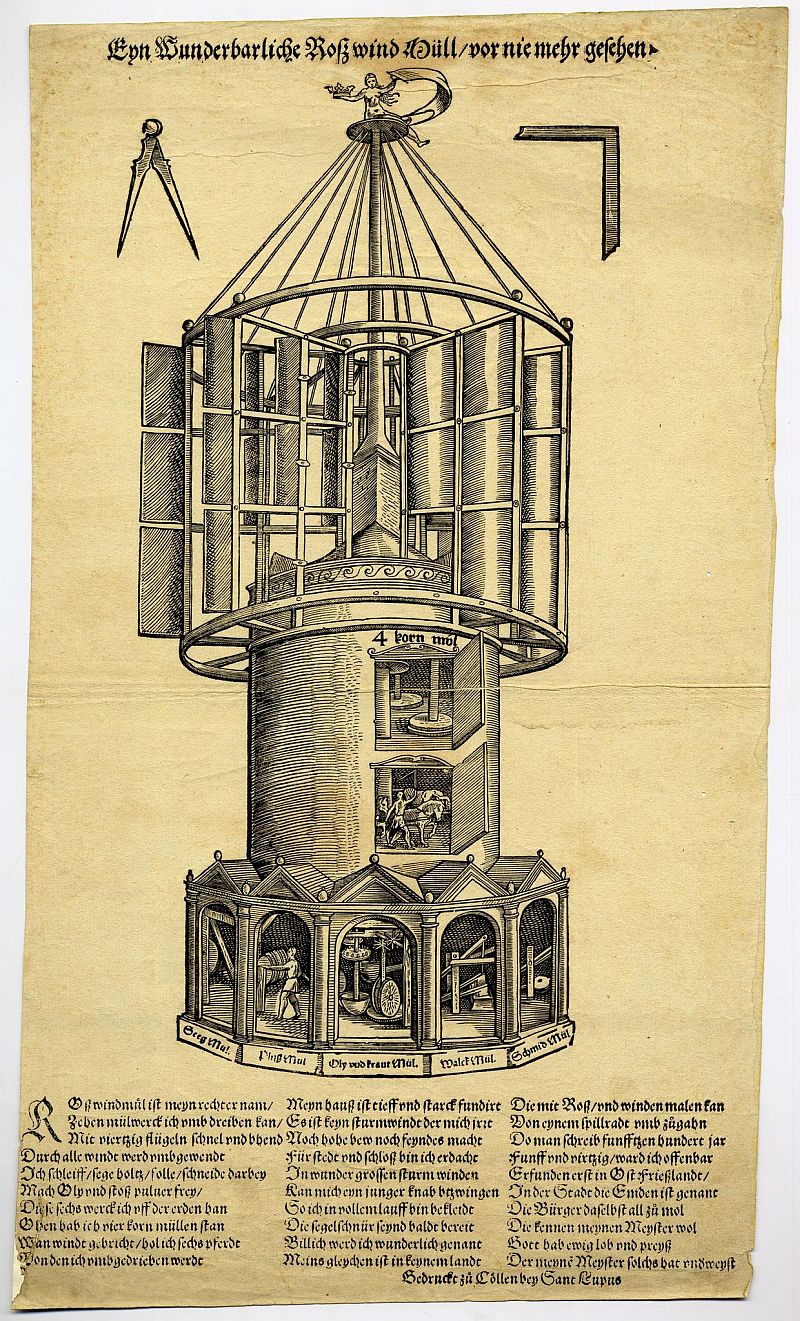
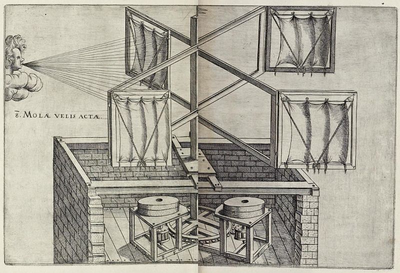
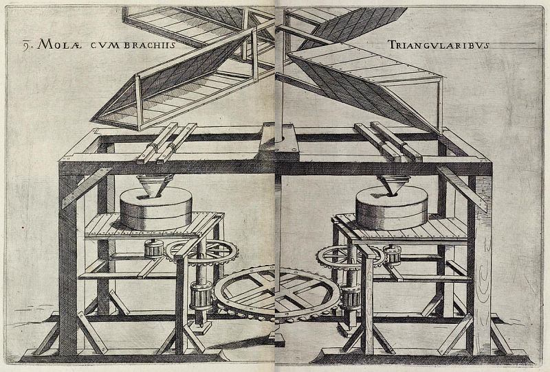

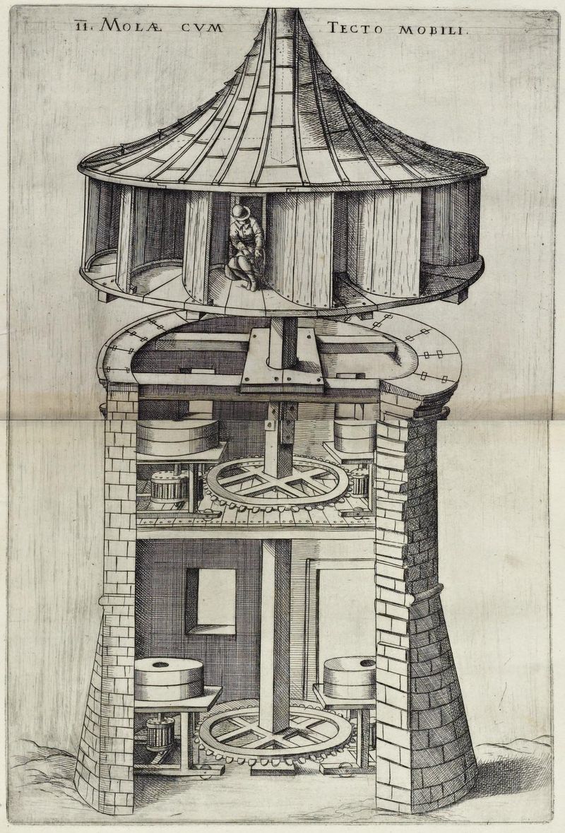
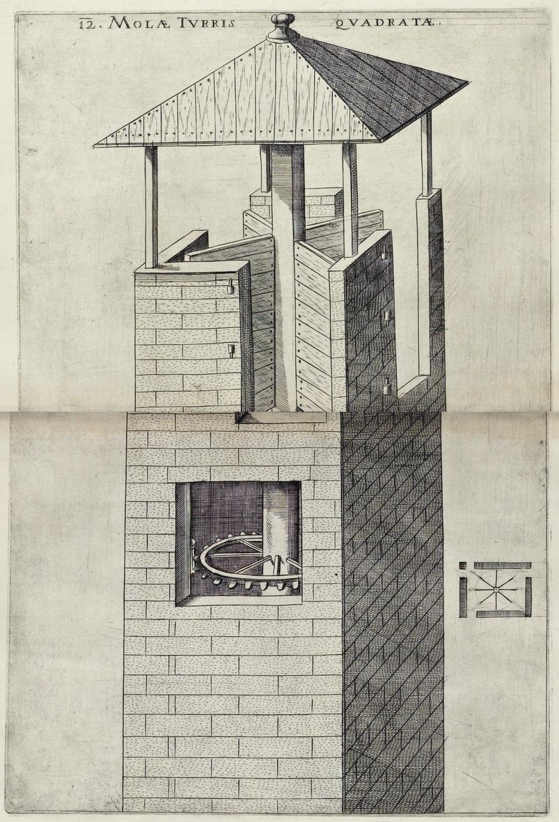

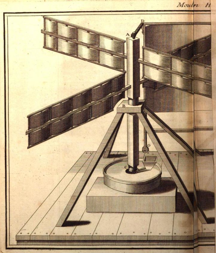
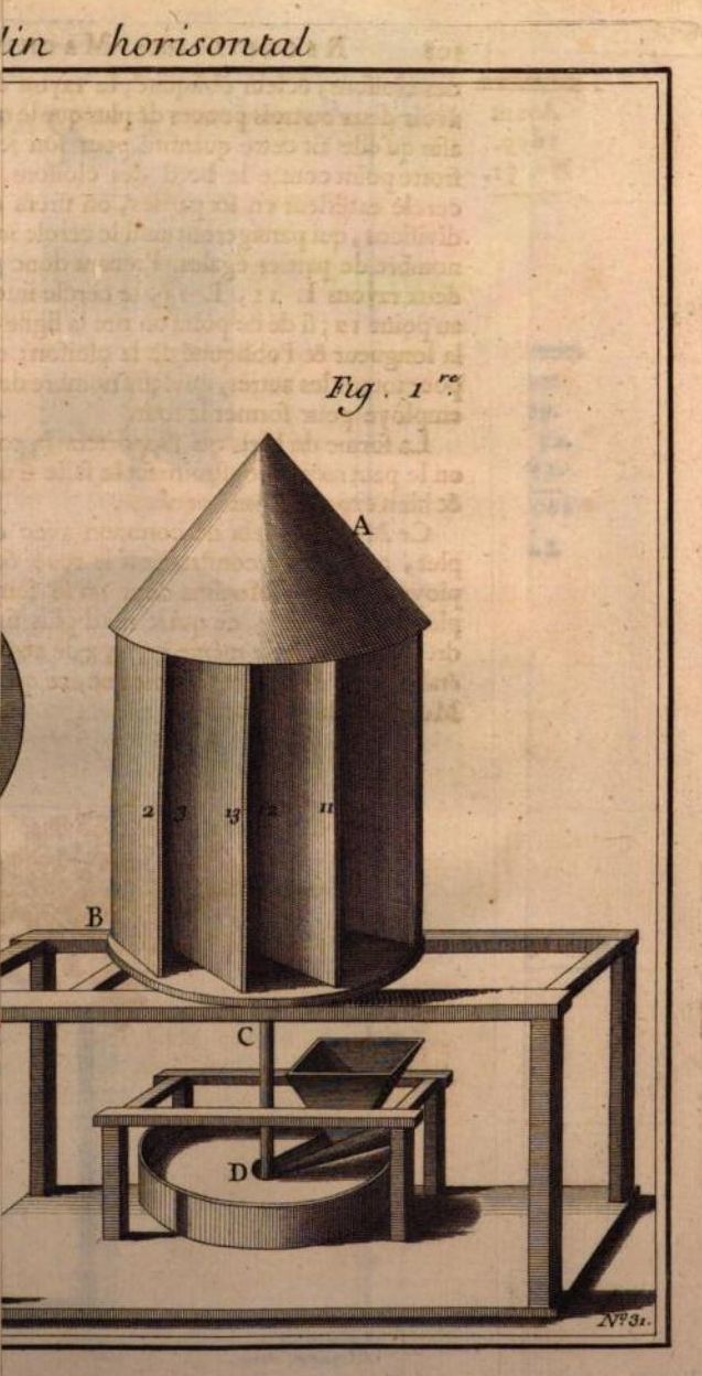
_Tafel_047.jpg)