
Other coverage of horizontal windmills:
Contents
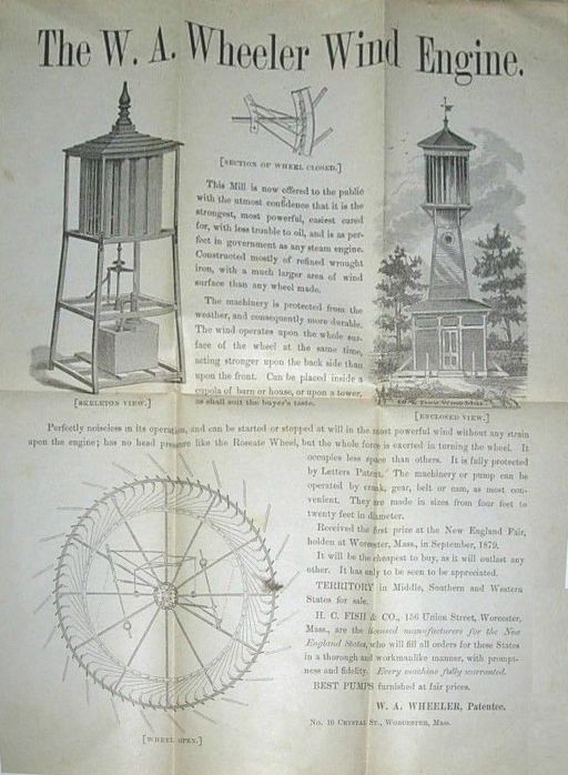
The W. A. Wheeler Wind Engine.
This Mill ls now offered to the public with the utmost confidence that it is the strongest, most powerful, easiest cared for, with less trouble to oil, and is so perfect in government as any steam engine. Constructed mostly of refined wrought iron, with a much larger ares of wind surface than any wheel made.
The machinery is protected from the weather, and consequently more durable. The wind operates upon the whole surface of the wheel at the same time, acting stronger upon the back side than upon the front. Can be placed inside a cupola of barn or house, or upon a tower, as shall suit the buyers taste. Perfectly noiseless in its operation, and can be started or stopped at will in the most powerful wind without any strain upon the engine; has no head pressure like the Roseate Wheel, but the whole force is exerted in turning the wheel. It occupies less space than others. It is fully protected by Letters Patent. The machinery or pump can be operated by crank, gear, belt or cam, as most convenient. They are made in sizes from four feet to twenty feet in diameter.
Received the first prize at the New England Fair, holden at Worcester, Mass., in September, 1879.
It will be the the cheapest to buy, as it will outlast any other. It has only to be seen to be appreciated.
TERRITORY in Middle, Southern and Western States for sale.
H. C. FISH & CO., 156 Union Street, Worcester, Mass., are the licensed manufacturers for the New England States, who will fill all orders for these States in a thorough aud workmanlike manner, with promptness and fidelity. Every machine fully warranted.
BEST PUMPS furnished at fair prices.
W. A. WHEELER, Patentee.
No. 10 CRYSTAL ST., WORCESTER, MASS.
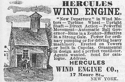
HERCULES WIND ENGINE.
"New Departure" in Wind Motors - Turbine Wheel - Upright Shaft - Direct Action - Powerful Movement - Automatic Ball Governor - Runs in a Zephyr - Effective in a Strong Gale. Power for ordinary pumping or for driving heavy machinery. Erected on Towers or built in Cupolas. Ornamental in design and a perfect ventilator. Agents wanted. Send for catalogue. Address,
HERCULES WIND ENGINE CO., 17 Moore St., NEW YORK
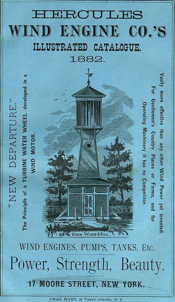
Hercules Wind Engine patent #233977, Nov 2, 1880HERCULES WIND ENGINE CO.'S ILLUSTRATED CATALOGUE. 1882.
"NEW DEPARTURE."
The Principle of a TURBINE WATER WHEEL developed in a WIND MOTOR.
6f FARM WIND-MILL.
Vastly more effective than any other Wind Power yet invented. For Gentlemen's Country Places or Farms, and for Operating Machinery it has no Competitor.
WIND ENGINES, PUMPS, TANKS, Etc.
Power, Strength, Beauty.
17 MOORE STREET, NEW YORK.
CHAS. HART, 36 VESEY STREET. N. Y.
UNITED STATES PATENT OFFICE.
CHARLES H. BURLEIGH AND WILLIAM A. WHEELER, OF WORCESTER, MASS.
WIND-ENGINE.
SPECIFICATION forming part of Letters Patent No. 233,977, dated November 2, 1880.
Application filed March 29, 1880. (No model.)
To all whom it may concern:
Be it known that we, CHARLES H. BURLEIGH and WILLIAM A. WHEELER, both of Worcester, in the county of Worcester and State of Massachusetts, have invented certain new and useful Improvements in Wind-Engines; and we declare the following to be a description of our said invention sufficiently full, clear, and exact to enable others skilled in the art to which it appertains to make and use the same, reference being had to the accompanying drawings, which form a part of this specification.
Our invention relates to improvements in that class of wind-engines known as "horizontal mills," and more especially those having vertical sails, pivoted so as to change their angular adjustment, and automatically regulated by governing mechanism; and the objects of our improvements are to provide a simple, sensitive, and practical governor mechanism adapted for operating the rim by which the slats are turned; to provide convenient facilities for stopping and starting the mill at pleasure; to perfect the details of construction, and provide a support for the sails of such nature as will render the wind-wheel light, rigid, and effective in its action.
We attain these objects by mechanism substantially such as illustrated in the accompanying drawings and hereinafter described, the particular subject-matter claimed being hereinafter definitely specified.
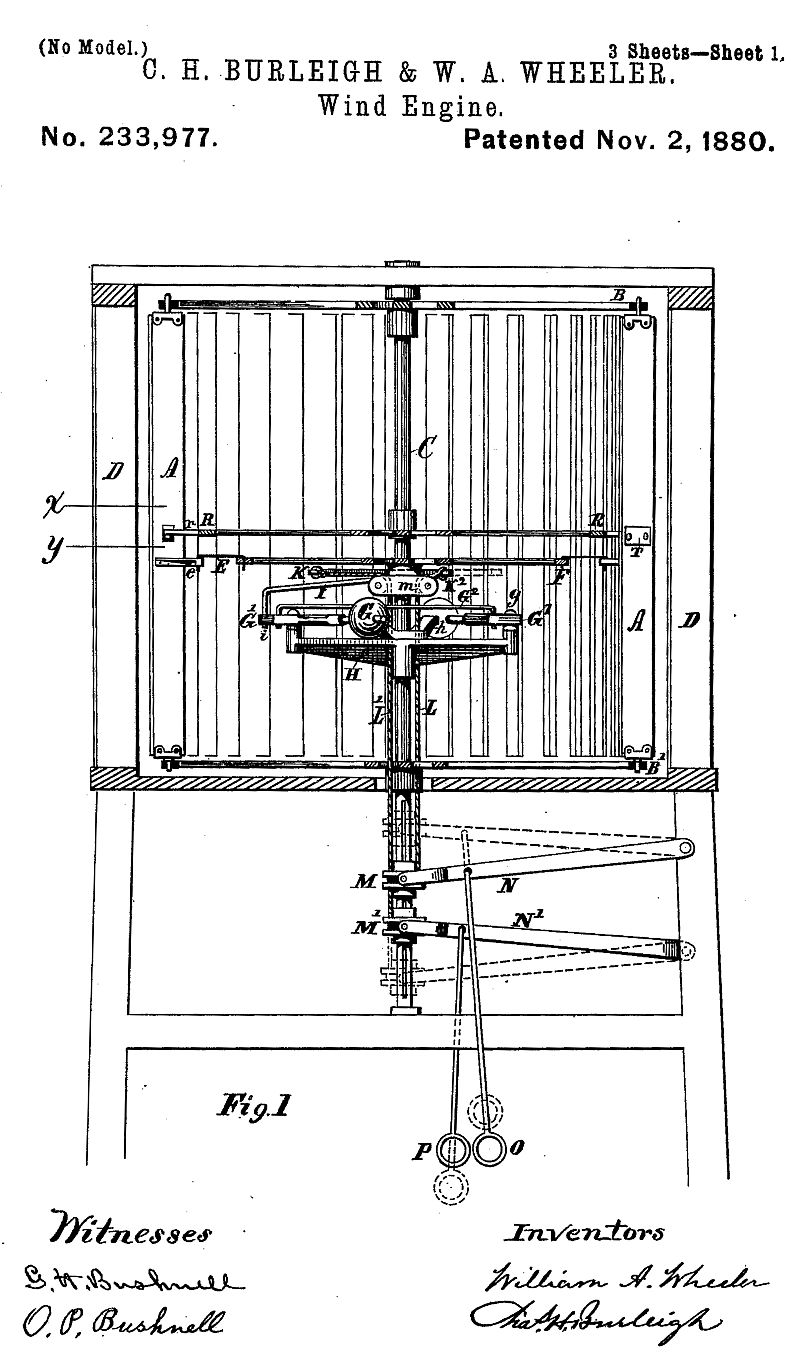
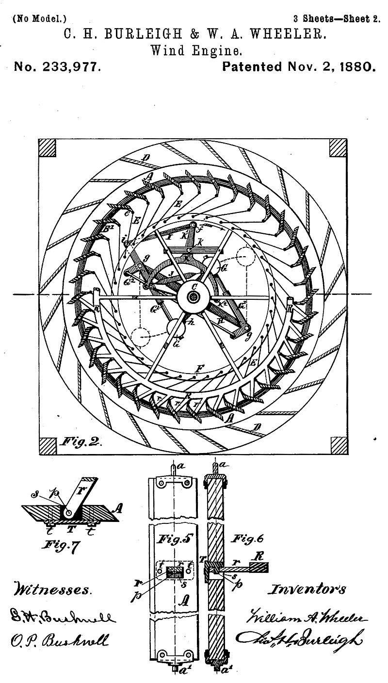
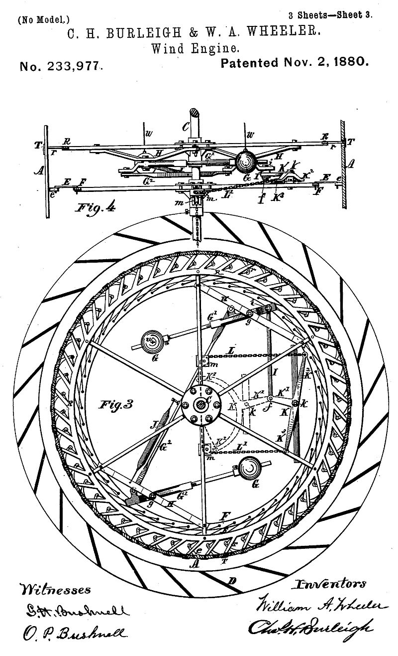
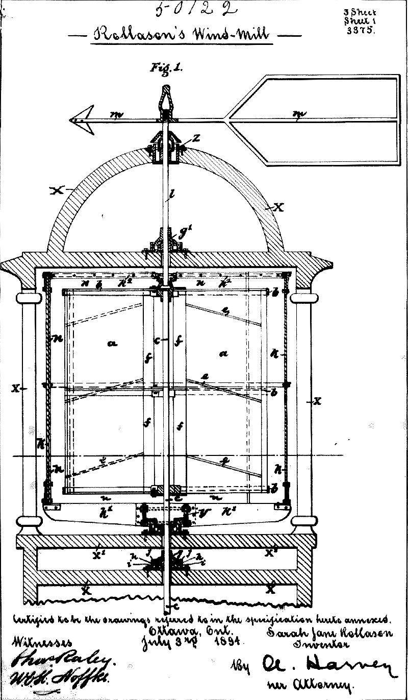
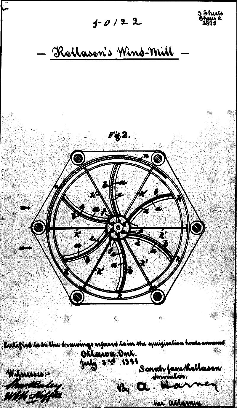
Figure 1 is a central vertical section of a windmill embracing the features of our invention. Fig. 2 represents a sectional plan view, showing the parts in position as with the sails open, one half being shown at the height x, and the other half at the height y, Fig.1. Fig. 3 is a sectional plan view, illustrating a modification adapted for large-sized wheels, and showing the parts in position as when the sails are closed for stopping the mill. Fig. 4 shows a side view of the governor devices and connections constructed similar to plan view, Fig. 3. Figs. 5, 6, and 7 are detail views illustrating the construction and arrangement of supports for sails.
In the drawings, A denotes the sail-slats; B.and B', the upper and lower end rims or sail-supporting wheels; C, the main shaft or axial support of the wheel; D, the cupola blind or deflector boards, arranged vertically about the tower, and E the operating-rods connecting the sail-boards or their arms e with the oscillating governor rim or wheel F. Said parts may be arranged and located in the manner shown, or substantially as described in Letters Patent No. 217,033. Their construction and operation need not, therefore, be herein more fully described.
Combined with the rim or wheel F, which is free to turn independent of the shaft C, we employ a governor mechanism located within the interior of the wind-wheel and constructed as follows: The weight or balls G are supported by horizontally-swinging levers G', fulcrumed at g to a cross-piece or support-bar, H, which moves with shaft C. Pivoted at i to the shorter arm of the lever G' is a connecting-rod, I, for operating the rim F and changing the adjustment of the sails as the balls G swing outward. Two weight-levers, G1, are preferably employed, set opposite each other and connected to work in unison by a link-bar, G2, thus requiring but a single set of connecting devices between the governor and rim F. A spring, J, or its equivalent, is provided for drawing the balls G and levers G1 inward, and to the proper degree resisting the centrifugal force. Said springs may be made adjustable, if desired. Stops or buffers h, of any suitable form, may be arranged to prevent the balls from swinging too far inward by the action of the springs.
In large machines, where the levers G1 are quite long, wires or rods w, extending to the top wheel-spokes, may be used to sustain the gravity of the balls and prevent excessive side strain on the levers G1. (See Fig. 4.)
K indicates a controlling-lever for changing the position of the rim F relatively to the point of connection of the governor devices, so that the sails A can be opened and closed independently and without strain on the governor mechanism. Lever K is pivoted or fulcrumed at k on a suitable supporting-piece attached to or forming a part of the rim-wheel F. Said lever is made with three arms, one of which, K', carries the pivot f, attaching rod I, which pivot is practically the point of connection between the governor mechanism and the sail-adjusting rim F. To the other arms, K' K3, of said lever are attached cords, chains, or equivalent connecting devices, L and L', which pass around sheaves m m, for changing their direction, and are carried downward near the shaft C, through suitable openings in the hubs and journals, to a position below the windwheel, where they are respectively attached to the hubs or collars M and M', that are arranged to slide toward and from each other along the shaft C, as indicated in Fig. 1. Forked levers N N' (or equivalent devices for converting a revolving to a stationary connection) are arranged for actuating said collars, from which pull rods or cords are carried to any convenient location, as desired, where they terminate in suitable handles, O and P, by means of which the controlling mechanism may be operated at will, as follows: When the handle O is drawn down, the lever N slides the collar M down the shaft, and the lever K is, by the draft on chain L, caused to take position, as shown in Figs. 1 and 2, with its arm K2 nearest to the shaft C, and the fulcrum k at the left of a radial line passing through the axis of the shaft C and connecting-pivot f. This brings the rim F to a position where the sails A will be open, as shown in Fig. 2, while the governor-balls G are at their inner position, resting on the stops h, the mill being then subject to the action and control of the governor mechanism; and as the speed of the mill causes the balls G to swing outward toward the position indicated by dotted lines, Fig. 2, the rim F will be moved by the rod I, and the sails thereby, to a greater or less degree, closed together, according to the force of the wind, giving greater or less speed to the wheel. When the handle P is drawn down, (see dotted lines, Fig. 1,) the lever N' slides the collar M' down the shaft, and the lever K is, by the draft on chain L', caused to assume the position indicated in Fig. 3, (dotted lines show a lever formed as in Fig. 2,) the arm K3 being drawn nearest to the shaft and the fulcrum k carried to the right of a radial line through the axis of shaft C and pivot f, thereby moving the rim F independent of the governor mechanism, so that the sail-slats A are closed while the balls G are in against their stops h. The relative position of the rim F and point of governor-connection f is thus changed or shifted by the swing of the arm K', so that the sails will remain closed, as shown in Fig. 3, until again opened by drawing the pull O or swinging the lever K to its former position. The mill can thus be stopped and started at will. The rod I might, if desired, be pivoted directly to the rim F, in case no controlling devices were needed. R indicates a rim or circle provided with a series of short inclined arms, r, for supporting and pivoting the sails. This rim R is retained by a central hub on shaft C, and a suitable number of radial spokes to keep it in proper position. The sails A are connected to the ends of the arms r by pivot blocks or castings T, arranged as indicated in Figs. 5, 6, and 7. Mortises or openings s are formed in the sail-boards A, into which the tongue part of the castings T and the ends of arms r are inserted from opposite sides of the sail, so that the pivot-pins p, which may be formed on either the arm or casting, will occupy a central position within the sail-board, or so that their axial lines will correspond with the axial lines of the upper and lower pivots, a a'. The flange or plate of the pivot-block T, through which the holding-screws or fastenings t t pass, rests upon the back of the sail, while the strain of the arm r is from the front, so that the force of the wind against the front of the sails tends to hold the pivot-blocks and sail-boards more firmly together instead of straining upon the attaching-screws t. The openings s are made somewhat deeper than the thickness of the arms and pivot-block tongues, so that by lifting up the sails the pivots p may be released from their holes and the sails readily disengaged from the arms r when desired. The inclination of the arms r from the rim R permits of the sail being swung around for their open and closed adjustment without interfering; and this, together with the manner of jointing, avoids the necessity of reducing the sail area by cutting off the sails to give space for the connections. The arms r being short, and also supported by the rim R quite near the sails, and the connections being made to support the sails in the manner set forth, permits of all of said parts being made comparatively light, while at the same time rendering the mechanism quite strong and rigid and supporting the thin narrow sail-boards firmly against springing or vibrating, while allowing their free action for adjustment. One, two, or more rims, R, with arms r, may be employed for supporting or for bracing the sails A, as desired. The rim provided with arms for supporting the sails, and the manner of connecting the sails thereto, are features of our invention.
If desired, the governor mechanism may be supported by the same hub or wheel which supports the rim R, as in Figs. 3 and 4, in lieu of a separate supporting-piece, as in Figs. 1 and 2, and the controlling lever or device K may be constructed and arranged in any convenient manner for changing the relative positions of the rim F and governor-connection by means of the pull devices, without departure from the spirit of our invention.
By connecting the arm K' to a part of the wheel or support HI the lever K and pull mechanism could be used for opening and closing sails in a mill having no governor.
What we claim as of our invention, and desire to secure by Letters Patent, is -
1. In a wind-engine, the combination of a series of narrow pivoted sails adapted to open and close, as set forth, an adjusting-rim, with connections for simultaneously operating said sails, and a governing device located adjacent to and connected to operate said rim, consisting of one or more weighted levers fulcrumed to swing in a plane perpendicular to the axis of the main shaft and to revolve with the wheel, and a counteracting spring or springs, whereby the rim and sails will be automatically adjusted, in the manner set forth.
2. The combination, with the governor mechanism and the adjusting-rim by which the sails are operated, of an intermediate controlling mechanism actuated by hand-pulls, substantially as described, for changing the position of said rim in relation to the governor-connection, and, independent of the governor devices, stopping and starting the mill, as set forth.
3. In a wind-engine, the combination, with the supports H, attached to and moving with the main wheel or shaft U, and the rim F, by which the sails are adjusted, of the levers G', fulcrumed at g and carrying balls G, connecting-rod G2, spring J, and bar I, for the purposes set forth.
4. The combination, with the governor-connection I and adjusting-rim F, of the lever K and pull-chains L L', for the purpose set forth.
5. The combination, with the governor mechanism and adjusting-rim, of the lever K, the chains L L', sheaves m, and sliding collars M M', for the purposes set forth.
6. The combination, with the sail-adjusting rim F, of the lever K, chains L L', collars M M', lever or forks N N', and handles O and P, for the purposes set forth.
7. In a wind-engine having pivoted sails, a circle or rim provided with a series of short arms for supporting or bracing said sails, substantially as set forth.
8. The combination, with the sails and sail-supporting arms, located intermediately between the ends of the sail, of the connecting-pivots, arranged centrally in relation to the thickness of the sail-boards, substantially as and for the purpose set forth.
9. The pivot-blocks or flanged castings T, constructed and arranged substantially as described, in combination with the mortised sail-slats A and supporting-arms r, as set forth, whereby the force of the wind is transmitted to the arms without strain on the attaching-screws t.
Witness our hands this 13th day of March, A. D. 1880.
CHAS. H. BURLEIGH.
WILLIAM A. WHEELER.
Witnesses : S. R. BARTON, J. A. RICE.
A LIST OF JOINT-STOCK COMPANIES REGISTERED AT SOMERSET HOUSE DURING MAY.The Engineer, April 20, 1894
Rollason's Wind Motor Company, Limited, £1 shares, 35,000
ROLLASON'S WIND MOTOR.Isle of Man Times, 12 March 1895
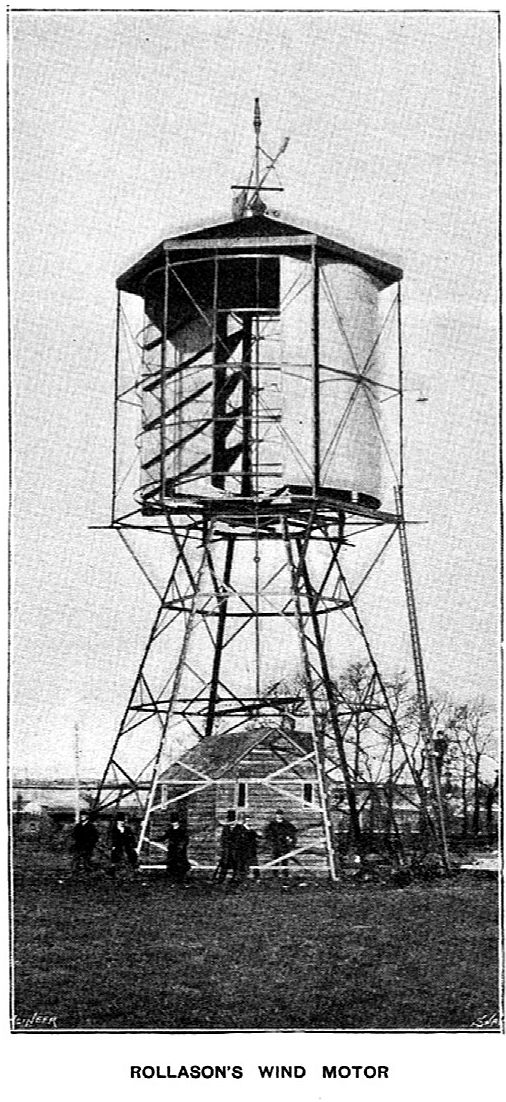
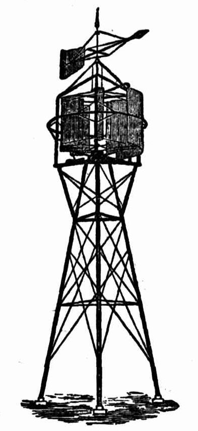
We recently had an opportunity of examining a new type of wind motor built by Rollason's Wind Motor Company, of Berners-street, London. The motor has been designed to produce motive power for electric lighting and other purposes, and a specimen has been built and erected in a large field close to Willesden Junction Station. A complete electrical installation, consisting of dynamo, accumulators, and switchboard, is installed in a wooden building at the base of the motor, and the outward appearance of the plant is shown in Fig. 1, which is taken from a photograph.The motor itself is supported upon a light structure built of angle and tee iron, provided with a roof to cover the working parts. The description naturally divides itself into two parts - firstly, that dealing with the motor itself with its transmission shaft and accessories; and, secondly, the electrical plant to which motive power is supplied.
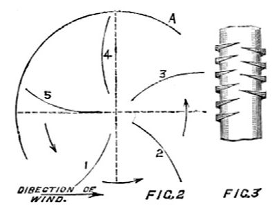
In designing the motor special care has been taken to make it as stable as possible in order to avoid danger of collapse in case of storms. The portion which receives rotary motion from the pressure of the wind consists of five wooden vanes, each vane forming a segment of a tube of very large diameter, and fixed so that it presents its concave surface to the direction of the wind. These vanes are fixed top and bottom to a five-armed star which is keyed to a vertical shaft. A space is left between the inner edge of each vane and the shaft itself, in order to allow for escape of air, and so that the centre of pressure may be as far from the axis of rotation as possible. In the present case each vane is 20ft. high, and the chord of the arc of section is 7ft. long, while from the inner edge of the vane to the centre of the axis is 7ft. Each vane thus exposes a surface of 140 square feet, and it is assumed that two vanes are in action at the same time, so that a surface of 280 square feet is exposed to the action of the wind. The vanes themselves are protected by a movable shield which covers 120 deg. of the whole circumference, and this shield is caused to take up a suitable position by the directive action of the wind upon an arrow-shaped vane at the summit.Fig. 2 is a diagram showing the relative shapes and positions of the vanes and shield in plan. The wind acts upon vanes 1 and 2 and partially upon 3, while the space between the shield A and vane 3 allows for the escape of the air. It is claimed that, therefore, about one-half of the motor is under pressure, and the other half in a calm. The vertical shaft which supports the movable shield is independent of the shaft upon which the vanes are fixed. The whole of the bearings consist of rollers arranged similarly to those used in turntables, and the castings containing the rollers are bowl-shaped, and are filled with oil in order to diminish friction. The vertical shaft is connected by bevel gearing and a horizontal shaft, which transmits power to a shunt-wound dynamo by means of belting. This dynamo is by the Electric Construction Corporation, and develops 65 volts and 35 amperes when running at a speed of 510 revolutions per minute. The dynamo is used for charging a set of accumulators, consisting of 26 E.P.S. cells of the K 15 type in teak boxes. The rest of the mechanism consists of automatic apparatus arranged with the view of making it possible to leave the motor unattended during considerable periods. The same difficulty has been met with as is always found in train lighting by electricity, owing to the varying speed of the dynamo. Large sums have been spent upon automatic apparatus for train lighting; it is, therefore, of interest to examine the method used in the present case. In a direct line with the armature shaft, and connected rigidly to it, is a light shaft provided with a centrifugal governor, which is made to control a double-armed switch, which travels over a series of contacts similar to those of the ordinary charge and discharge switch. With this apparatus it is considered that it will be possible to switch cells in or out according to the pressure produced by the dynamo. We now come to the case in which the cells are being charged, and it is desired to stop the dynamo automatically after a complete charging. This apparatus is somewhat complicated, and although ingenious, we fear it will be liable to get out of order. The whole control is obtained from the rise and fall of an ordinary hydrometer in the electrolyte, a movement due of course to the changing specific gravity of the liquid as the process of charging proceeds. As soon as the liquid attains its greatest density the hydrometer rises and closes a small contact, which permits a current to pass through a relay and releases a switch, breaking the circuit through the relay and actuating a clutch which puts clockwork into motion. This clockwork may be set to run for two, three, or four hours as desired, and during that time the cells are still receiving a charge so as to cause thorough boiling. At the close of this period, when it is desirable to cease charging altogether, the clockwork actuates a switch which permits a current to pass into an electro-magnet controlling the belt fork gear. The belt gear is an ingenious contrivance, and has a right and left-handed interrupted or mangle screw. Over one half of the superficies of the screw spindle the left hand pitch predominates, and over the other half the right-hand thread, while upon two lines parallel with the axis there is no thread, as indicated in Fig. 3. Of course, in cutting one thread the other is partially cut away, and the portions of threads end in sharp points. At each side of the screw, which is driven by belting, is placed a half nut normally out of gear with the screw, but put into gear suddenly by the action of one or other of two electro-magnets. To return to the clockwork for a moment, we observed that it causes a circuit to be closed when the cell charging is completed, the current then passes through one of the electro-magnets, and by means of the double-threaded screw the belt fork moves the dynamo belt on to a loose pulley, thus leaving the wind motor itself perfectly free to rotate without doing any work. If power is being taken from the cells the density of the electrolyte will fall, and finally the hydrometer will close a lower contact which causes the belt to be put again upon the fast pulley and the dynamo to be restarted. The whole apparatus is theoretically perfect, but we are much afraid that the delicacy of the parts will lead to trouble. Messrs. Rollason, however, are upon the right track, and if they can devise a simpler mechanism should succeed. It must always be remembered that for such a wind motor and electrical plant to be of use it must be simple enough to be attended to by a gardener. If a skilled mechanic or electrician is needed it will much diminish its chances of usefulness. We hope to have an opportunity on a future occasion of describing the details more fully with the aid of illustrations, and it must be remembered that the plant we examined was the first built by the company, and therefore somewhat crude. We are informed that Messrs. Edmundsons, of Great George-street, Westminster, have carried out the whole of the electrical work required. There should be great scope for a successful and really trustworthy wind motor for electrical purposes, and we understand that a number of orders has already been received by the company, which is about to start works close to Willesden Junction station, where it will manufacture the complete plants.
The Rollason was sold at a premium price, as this mention of it at the Royal Agricultural Show at Darlington notes. North Star (Darlington), 24 June 1895The Rollason Wind Motor
Wind Motors for Electricity, &c.
We have great pleasure in calling the attention of our readers to the Rollason Wind Motor, a recent invention which presents infinite possibilities for the working of electric lighting installations, and for pumping, grinding, irrigation, and other machinery. Our illustration gives such a good idea of the mill, that a prolonged description is unnecessary: but we may say this form of motor is quite a departure from the ordinary construction of wind mills which are now in use, it being a horizontal design or arrangement erected within a skeleton turret. From the top to bottom of the centre or axis of the turret is provided a vertical steel shaft having five concave sails attached, which revolve on radius rollers immersed in oil. On these sails are fixed a number of inclined ridges or planes, which defect the force exerted by the wind to their peripheries. Between the sails and the shaft is arranged a considerable open space which allows the wind to actuate three sails out of the five, at the same time. Outside the sails is a framing supported by six radial or cross arms, which are bolted to a centre bearing which is free to rotate independently of the sails. From the top of this shield is a second vertical shaft continued through the roof of the turret, and to this is fixed a vane, so that when the direction of the wind changes it moves the shield into the correct position for only the concave sides of the sails to catch the wind. On the top of the sail shaft is fixed a cup containing a quantity of oil, within which are rollers by which the shaft actuates the shield. The weight of the vane shaft is carried on an independent roller bearing fixed in the roof of the turret. The whole weight of the sails and framing carrying the shield, is thrown to the centre bearings on the bottom of the turret, which thus gives to the working parts of the motor the desired balance.
The salient advantages of this invention are, its simplicity of construction, efficiency in working, the few working parts, which, further, are arranged to run in oil so as to be always lubricated and prevent corrosion; it can, therefore, be left working for a lengthy period without any attention; its capability of taking up a breeze or accommodating itself to a gale, its ready adaptability for erection on buildings, as the turret can be built to suit any style of architecture.
The motor working at Willesden Junction is 20ft. in diameter, and is erected on an open iron structure, 30ft. high, and is being used for generating electricity for lighting purposes. The power developed by the motor is transmitted by a vertical shaft running down the centre of the supporting frame into a wooden building on the ground. On the lower end of the shaft is provided suitable gearing for working the necessary mechanism for driving the dynamo which charges accumulators of sufficient capacity to provide for a calm or an extremely light breeze.
There are, further, several automatic arrangements and special features to be noted in connection with the electrical apparatus to which the motor is applied. e g. :-
In factories, where motive power is required, the electricity generated can be used in the summer or daylight. when no light is required, for driving machinery of various kinds, or for other similar purposes where the electric current or power can be utilised. Obviously the power obtained by the motor can be also employed as a mechanical agent for working pumps or other machinery. The efficiency, lightness, cheapness and facilities of erection are other advantages of this particular type of wind turbine motor.
- That for di-connecting the dynamo from the accumulator when the wind drops;
- That for charging and lighting at the same time:
- That for stopping the dynamo when the accumulators are fully charged, and for restarting it as soon as any current is used from the accumulators, the object being to let the combined motor and electrical plant work all night, and on Sundays, without any attention.
A motor of this kind ought to be of enormous value in this Island, more especially in the country districts, to which the carriage of coal is so expensive that steam power is practically forbidden on account of the great outlay. If the motor will perform only half what is claimed, it should very soon win its way into general adoption.
We may add that we contemplate the erection of one for electric lighting in connection with our premises.
THE ROYAL SHOW.A court appearance - no details found yet: London Evening Standard, 06 February 1896
SUCCESSFUL OPENING.
AMONGST THE IMPLEMENTS
BY PROFESSOR LONG.
...
THE WIND MOTOR: REMARKABLE MACHINE.
Rollason's Wind Motor Company, of London, exhibit one of the most remarkable machines in the Show-yard in the form of a horizontal wind motor with a huge screen and cap, and sails of unusual form. These sails, by pressing the solid surface to the wind, obtain more power, and the greater the force of the wind the greater the power obtained, which is not exactly a feature connected with every motor of the same kind. But for the price this machine would perhaps be used to a considerable extent. Another firm, Messrs Millar, of Dumfries, exhibit a wind-mill on the American principle, and indeed made in Illinois, which is extremely useful for pumping and for work of a light nature. But the same mill, although manufactured in a country where wages are perhaps 50 per cent. higher, is considerably more expensive than in America.
Law Notices - This Day.Also in the notices for the 11th. Western Morning News, 20 May 1896
LORD MAYOR'S COURT.- At 10 1/2.- ... Cobbett v Rollason's Wind Motor Company (Limited)
    DEVON COUNTY SHOW.
    AT STAND 109
    Is being exhibited
    ROLLASON'S PATENT WIND MOTOR,
    So extensively used for
    LIGHTING, PUMPING, GRINDING, AND DRIVING
    ALL KINDS OF
    AGRICULTURAL MACHINERY.
    INSPECTION SOLICITED
Transactions of the Highland and Agricultural Society of Scotland, 1896
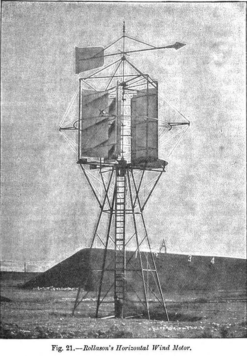
The horizontal wind-motor is a more recently introduced form of wind-engine. An illustration of Rollason's wind-motor (fig. 21) gives a good idea of its form. Each sail presents a solid surface to the wind, and, being concave, forms a box to hold the wind; the deflectors lying at an angle cause the wind on the sails to push with force to the peripheries, thus giving increased force. Five sails are provided, three of which are always in the wind. The open space between the sails and the shaft permits the wind to actuate the distant sail. The convex side of the sails is protected from the wind by the screen, which is actuated and kept in the proper position by the rudder. Half the motor is protected from the wind although the screen is only one-third the size of the circumference. Although the screen offers resistance to the wind, the fact that the sails revolve horizontally, ensures the safety of the engine, because, as in the case of the common spinning-top, the faster it rotates the greater is the tendency to the perpendicular.The location of this installation is not given, but there are numbers 1,2,3 and 4, and the letter A on a man made earth bank in the background - this looks like an Army firing range, where targets are often so identified. I suspect this is the Rollason wind-motor installed at the Rifle Range at Gravesend Not much new information in this report from Australia, but it does have a different tower illustrated, and indicates that it was seen at the Smithfield Exhibition, which would be the annual agricultural show held by the Smithfield Club at the Agricultural Hall, Islington, London. Leader (Melbourne), 11 Jul 1896, Page 12
A motor 8 feet in diameter, and sails 5 feet in height, will raise with wind at 16 miles an hour 125 gallons of water 80 feet through a 2-inch single pump. The illustration shows a 20-feet motor working a complete plant of fifty 16-candle power incandescent lamps, which has been running two years. Its power can therefore be fairly well gauged; and its serviceability for producing motive power, such as could be advantageously utilised on the farm, may be estimated.
Messrs Rollason calculate that with a wind of 16 miles per hour, an 8-feet motor is equal to 1/4 horse-power; 10-feet to 1 horse-power; 15-feet to 2 1/4; and 20-feet to 5 horse-power.
THE NEW WIND MOTOR.
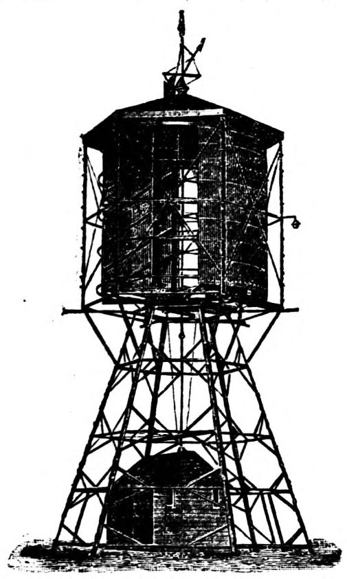
Our illustration shows the Rollason wind motor, which was exhibited at the last Smithfield Exhibition. This form of motor is quite a departure from the ordinary construction of wind mills now in use, it being a horizontal design or arrangement erected on a tower within a skeleton turret. From the top to bottom of the centre or axis of the turret is a vertical steel shaft having five concave sails attached, which revolve on radious rollers immersed in oil. On these sails are fixed a number of inclined ridges or planes which deflect the force exerted by the wind to their peripheries. Between the rails and the shaft is a considerable open space which allows the wind to actuate three sails out of the five at the same time. Outside the sails is a screen supported by six radial or cross arms bolted to a centre bearing, which is free to rotate independently of the sails. From the top of this screen is a second vertical shaft continued through the apex of the turret and to this is fixed the vane L, so that when the direction of the wind changes it moves the screen by the arms into the correct position for the concave sides only of the sails to catch the wind. On the top of the sail shaft ia a cup containing oil, within which the shaft rotates. The weight of the vane shaft is carried on the roller bearing. The whole weight of the sails and framing supporting the screen is carried on the centre bearing at the bottom of the turret and tower, which thus gives to the working parts of the motor the desired balance and stability.
THE AGRICULTURAL SHOW ON THE SOUTHAMPTON COMMON.
SUCCESSFUL INAUGURATION.
...
Windmills of different types tower to a good height, and were exhibited by Messrs. Duke and Ockenden, Littlehampton, Messrs. E. and H. Roberts, Stony Stratford, and the Rollason's Wind Motor Company, London.
MOTOR WINDMILLS.
The North-Eastern Railway Company are now making an interesting departure in the mode of pumping water at several of their stations. Arrangements have been concluded for the installations of a number of wind-motor mills, which, it is claimed, will work in any gale, and also in a lighter wind, and are more economical and effective than any other apparatus.
The rotating part of the mill works on a horizontal plane, the revolving part being fixed within a skeleton turret. From the top to the bottom of the centre of the turret is a vertical steel shaft, having five concave sides attached, which revolve on rollers.
Between the sails and the shaft is a considerable space which allows the wind to actuate three out of the five sails. Outside the sails is a screen supported by six cross arms, which is free to rotate independently of the sails.
From the top of this screen is a second vertical square shaft, continued through the apex of the turret, and to this is fixed the vane, which, upon the direction of the wind changing, moves the screen by the arms, so that the concave sides of the sails catch the wind. Three of the four working parts in the motor move only as the wind changes.
SHAREHOLDERS AND THEIR LUNCHEONS.
Before Mr. Justice Channell, the case of Sanderson v. Rollason was heard. Mr. Newson, for the plaintiff, said the action was brought against Mr. C. A. Rollason, managing director of the Rollason Wind Motor Company, to recover £31 odd, the cost of 25 luncheons supplied to shareholders by the plaintiff, who conducts the Royal Oak Hotel, Harlesden. Plaintiff's evidence was that in September, 1897, he received a telegram from the defendant to supply his "celebrated luncheon" for the numbers mentioned. He did so, and was told that the persons present at it represented several millions of money. He was asked to put money into the concern, and he said he did not mind putting in £100. In cross-examination he said the company, which numbered 25, consumed 32 bottles of wine, in addition to spirits. - The defendant was called by Mr. Gregson Ellis and said his company's works were at Willesden. They had an informal meeting of shareholders at Birmingham in September, 1897, and decided to have luncheon in London on the following day. That was in connection with the obtaining, of more capital and reconstructing the company. He telegraphed to the plaintiff and also saw his manageress, who asked him who the luncheon was for. He told her it was for the company. The order for the wine was given by Mr. Fletcher, the chairman of the company. - Cross-examined: The telegram he sent ordering the luncheon was signed "Rollason"; but that was the telegraphic address of the company. He believed he had the authority of the company to order the luncheon; but he could not produce any minute - book showing any such instructions. - Mr. W. H. Fletcher, chairman of the company, said he was present at the meeting at Birmingham when the luncheon was decided upon. He ordered the wine at the luncheon. - Mr. George Rollason, another director, said be thought it was in order for the Birmingham shareholders to order the luncheon. His Lordship said the company could not reasonably be held to be liable, and he found for plaintiff.
MODERN COMPANY PROMOTING METHODS.
Story of a Champagne Luncheon.
Yesterday afternoon Mr. Justice Channell heard an action brought by Mr. William Sanderson, proprietor of Royal Oak Hotel, Harlesden, against Mr. C. Rollason, managing director of the Rollason Wind Motor Company (Limited), for £35, the cost of a champagne luncheon.
Plaintiff's case was that just before Christmas last year he provided a luncheon for 20 persons and about 30 bottles of wine, including champagne, a number of boxes of cigars and cigarettes were consumed. Mr. Sanderson was induced to apply for 100 shares in the Wind Motor Company on the representation that sitting round the table on the day of the luncheon were gentlemen who had command of capital amounting to between eight and nine millions of money.
Defendant denied that the luncheon was ordered by himself. It was a banquet given by the company to several shareholders who it was thought might subscribe more money to the undertaking.
His Lordship - Seeing that each person consumed considerably more than one bottle of champagne, it is quite evident you wanted these people to put money into the company.
Defendant - A number of them did, my Lord. (Laughter.)
His Lordship - I'm not surprised to hear it.
Judgment was given for the full amount, with costs.
DISPUTE ABOUT A LUNCHEON.
In the Queen's Bench Division of the High Courts of Justice yesterday the case of "Sanderson v. Rollason" came on for trial before Mr. Justice Channell.
Mr. Newson appeared for the plaintiff, and Mr. Gregson Ellis for the defendant.
The plaintiffs were the proprietors of the Royal Oak Hotel Harlesden, and they sued Mr. Charles Arthur Rollason, of 6, Fairlight-avenue, Acton-lane, Harlesden, to recover 31l. 3s. 9d. for spirits supplied, and for a luncheon given to 20 or 25 people shareholders in the Rollason Wind Motor Company, of Berners-street, which had works in the vicinity of Harlesden, and of which the defendant was one of the managing directors. According to the evidence of Mr. William F. Sanderson, a member of the plaintiffs' firm, on February 7th, 1897 the defendant ordered a bottle of whisky and a bottle of brandy, of the value of 8s. 6d., which were sent to the defendant's house. In September the defendant wired "I want one of your famous luncheons for about 20 tomorrow at one o clock," and defendant called the same evening and confirmed his telegram. A luncheon had been given by Mr. Fletcher, the chairman of the company, some two or three years before. The luncheon was supplied to some 25 people, and the cost of it was debited to the defendant, who, however, asked, after the invoice had been forwarded to him, that it should be sent to the company in Berners-street. The credit was, however, given to the defendant, who did not, when ordering, say anything about the company.
In cross-examination the plaintiff said that Mr. Rollason had been a customer for some time, and had paid for what he had at the time. There was no entry against him before this. He did not send the invoice to the company until requested by the defendant to do so. He did not know that the chairman ordered all the wine.
In re-examination the witness said the defendant asked him if he knew the amount of capital represented in the room, and on his saying he did not, told him that it was about eight or nine millions. The meeting had something to do with the reconstruction of the company, and those present were subscribing capital, and on being asked witness said he would put his name down for 100l. The only thing he heard about it was a letter asking for two guineas for expenses which he considered was adding insult to injury, and put it into the waste paper basket.- (Laughter.)
After other evidence,
The defendant was called, and said the company was still young and going well. He didn't give the order for the whisky and the brandy, which was never received at his house. They had an informal meeting at Birmingham of some of the shareholders, and it was arranged that some of them should come to London, and, in consequence, he sent the telegram. All the directors were at the meeting and it was a company matter. When he called, after sending the telegram, he saw the manageress, and she asked who it was for and he gave her a card of Rollason's Wind Motor Company. The plaintiff spoke to him through the telephone at the works that evening, but he did not see him till the meeting. Mr. Sanderson was in the room during the lunch and the chairman ordered the wines and cigars. He did not receive any account from plaintiff until after it had been sent to the company, and the plaintiff, on sending the account on to the company, asked him if he thought Mr. Fletcher would think it was too much. Witness said he did not think so.
Cross-examined.- He did not produce the minutes of the company authorising the expenditure. The company had not paid Mr. Saunderson, because he understood they said he was indebted to the company. He was not responsible for the debts of the company, although he was one of the vendors to, and promoters of, it. He denied that he asked the plaintiff to send the account on to the company after receiving it himself. The meeting was on behalf of the company, and the object was to get more money.
The learned judge said he supposed he might exercise his own judgment, that it was to get them to subscribe some money, as there were over 30 bottles of wine for 25 people, besides brandy and whisky.- (Laughter.)
The defendant said a lot of people came in late after the luncheon.
Mr. Fletcher, the chairman of the company, gave evidence to the effect that he ordered the wines and cigars, and after some other evidence, it having been pointed out that there had been no proof given of the delivery of the bottles of spirits, plaintiff's counsel did not press that part of the claim.
The learned judge gave judgment for the plaintiffs for 30l. odd, the cost of the luncheon, stating that, in his judgment, it was not the business of the company at all.
Judgment for the plaintiffs, with costs accordingly.
Mr. Justice Channell decided yesterday in the case of Sanderson v. Rollason, to recover £31 for the cost of 25 luncheons supplied to shareholders of the Rollason Motor Company, that the company could not be held liable, and gave judgment for plaintiff against Mr. Rollason, the managing director.
...
BIRMINGHAM SHAREHOLDERS AND THEIR LUNCHEONS.
32 BOTTLES OF WINE FOR 25.
In the Queen's Bench Division yesterday, before Mr. Justice Channell, the case of Sanderson v. Rollason was heard. Mr. Newson, for the plaintiff, said the action was brought against Mr. C. A. Rollason, managing director of the Rollason Wind Motor Company, to recover £31 odd, the cost of 25 luncheons supplied to shareholders by the plaintiff, who conducts the Royal Oak Hotel, Harlesden.
Plaintiff's evidence was that in September, 1897, he received a telegram from the defendant to supply his "celebrated luncheon " for the number mentioned. He did so, and was told that the persons present at it represented several millions of money. He was asked to put money into the concern, and he said he did not mind putting in £100. - In cross-examination he said the company, which numbered 25, consumed 32 bottles of wine, in addition to spirits.
The defendant was called by Mr. Ellis and said his company's works were at Willesden. They had an informal meeting of shareholders at Birmingham in September, 1897, and decided to have luncheon in London on the following day. That was in connection with the obtaining of more capital and reconstructing the company. He telegraphed to the plaintiff and also saw his manageress, who asked him who the luncheon was for. He told her it was for the company. The order for the wine was given by Mr. Fletcher, the chairman of the company. - Cross-examined: The telegram he sent ordering the luncheon was signed "Rollason," but that was the telegraphic address of the company. He believed he had the authority of the company to order the luncheon, but he could not produce any minute book showing any such instructions. The Birmingham meeting was informal, and the Birmingham shareholders brought friends with them.
The Judge: As you had a good deal more than a bottle of champagne apiece, I suppose you got the people to subscribe more money! - Yes.
Mr. M. H Fletcher, chairman of the company, said he was present at the meeting at Birmingham when the luncheon was decided upon. He ordered the wine at the luncheon.
Mr. George Rollason, another director, said he thought it was in order for the Birmingham share holders to order the luncheon. It was a Birmingham company really.
His Lordship: Which lunches in London - (laughter).
After some slight argument his Lordship said the company could not reasonably be held to be liable, and he found for plaintiff for the amount claimed, the costs on the High Court scale.
ACTION BY A LONDON SOLICITOR.
Guildford E. Lewis, solicitor, Gray's Inn, sued Colonel Burton Brown, of Loughborough, to recover £36 19s. 9d., professional costs incurred by the plaintiff. - Mr. Blaiklock, barrister, who represented the plaintiff, stated that the claim was made up of two items, one of £9 7s. 6d., bill of costs directly incurred by the defendant, and £27 2s. 3d., an agreed proportion of a bill of costs, in an action brought by the late Sir Alexander Armstrong (of Sutton Bonnington), and Colonel Brown, against the Rollason Wind Motor Company, Limited, of which both were directors. There was a difficulty in obtaining directors fees, and plaintiff was instructed to recover for Sir Alexander the sum of £465. The amount due to Colonel Brown was £280, and plaintiff was consulted in the matter. Defendant was a witness in the case of Sir Alexander against the company, and a suggestion was made that the costs of both should be shared. It was stated that probably if a judgment was obtained by Sir Alexander a similar result would follow should Colonel Brown issue a writ to recover his fees. Colonel Brown objecting to share costs equally it was agreed that he should pay pro rata. - Judgment was obtained in Sir Alexander's case, and also in Colonel Brown's. Mr. Blaiklock said he believed Colonel Brown's defence was that costs were only incurred after February 7th. - The plaintiff gave evidence at some length in support of his counsel's statement, and produced a letter showing that the defendant had agreed to terms with respect to sharing the costs. - in Sir Alexander Armstrong's case judgment was obtained, as it was also in the case of Colonel Brown. Since the action plaintiff had written informing Colonel Brown of his share of the costs in Sir Alexander's case, which, with other costs, made up a total of £36 19s. - Cross-examined: Plaintiff admitted that he first became acquainted with the defendant through the case of Sir Alexander Armstrong, but plaintiff did not first suggest that defendant should himself enter an action. Plaintiff did not obtain costs from the company in recovering the directors' fees, but he was now willing to reduce his claim to £32 2s., being defendant's proportion of the costs. - Answering his Honour, defendant stated that he had paid £21 2s. 1d. into Court.
(Proceeding.)
T. C. WILLIAMS AND SONS, LTD. - In our 3rd page will be found a prospectus setting forth the particulars of this newly formed Company, the object of which is to further develope the old-established iron and brass foundry and engineering business in London-street, and also to develope the manufacture of Rollason's Patent Wind Motor. The share capital is divided into 4,000 6 per cent. cumulative preference shares of £1 each and 16,000 ordinary shares of £1 each; total £20,000. The freehold premises, plant, machinery and good will are valued at £11,550.
T. C. WILLIAMS & SONS, LIMITED,
HEATING, VENTILATING, ELECTRICAL AND GENERAL ENGINEERS, IRON AND BRASS FOUNDERS, LONDON STREET IRON WORKS, READING.
Churches, Mansions, Public and Private Buildings, Swimming Baths, &c., Heated by either High or Low Pressure Hot Water, Warmed Air, or Steam.
Cooking Apparatus of all descriptions. Kitchen Ranges, Grills, Steam Tables, &c.
Pumps and Pumping Machinery for Water or Sewage.
Sole Makers of ROLLASON'S PATENT WIND MOTOR, for Pumping, Grinding, and Driving Machinery.
Complete Installations of ELECTRIC LIGHTING or WIRING ONLY, for all descriptions of Buildings.
ELECTRIC MOTORS for driving Machinery.
Castings of all descriptions in Iron, Brass, Gun Metal, Bronze, &c.
LONDON STREET IRON WORKS, READING.
T. C: WILLIAMS AND SONS, LIMITED,
LONDON STREET IRONWORKS, READING,
will EXHIBIT at the ROYAL COUNTIES SHOW, READING,
ON JUNE 10th and FOLLOWING DAYS (STAND No. 35, SHED 3),
A SELECTION OF THEIR IMPROVED KITCHEN RANGES, RADIATORS,
AND A ROLLASON PATENT WIND MOTOR.
All information given at the Stand.
T. C. WILLIAMS &SONS, LIMITED.
LONDON STREET IRONWORKS, READING.
LONDON OFFICE :- PALACE CHAMBERS, BRIDGE STREET, WESTMINSTER.
D. A. PETRIE & CO.
Beg to announce that they have acquired the Old Established Business of T. C. WILLIAMS & SONS, LIMITED
LONDON STREET IRON WORKS, READING,
And In conjunction with Mr W. W. WILLIAMS intend continuing the business of - IRON and BRASS FOUNDERS.
Castings of all descriptions in Iron, Brass, Gunmetal, Bronze, etc., Columns, Fencing, Manhole Covers, Gratings, Tanks to 50,000 gallons capacity, Machine Castings, etc. HEATING and VENTILATING ENGINEERS.
Churches, Mansions, Public and Private Buildings, Conservatories, Greenhouses, etc., heated by High or Low Pressure Hot Water, Warmed Air or Steam, Hot end Cold Water Supply, Radiators, etc. KITCHEN RANGES & COOKING APPARATUS.
Makers of the improved Close Fire Ranges, Grille, Hot Plates, Steam Tables, Closets, etc. GENERAL ENGINEERS.
Manufacturers of Pumps and Pumping Machinery, Rollason's Patent Wind Motors, Sewage Pumps, and Machinery, Steam, Oil and Gas Engines by all the principal Makers, Fire Maine Hydrants, etc., Electric Installations, Electric Motors, IRON & STEEL CONSTRUCTIONAL WORK.
Wrought Iron Roofs, Fire Escape Staircases, Smiths' Work, Ornamental Iron Work, Girder, Stanchions, etc.
D. A. PETRIE and COMPANY
beg to solicit inquiries and orders for the above, and assure their Customers that with the aid of a very efficient Staff in all departments, and personal attention to all orders, they hope to secure a continuance of those favours so liberally bestowed on their predecessors.
LONDON STREET IRONWORKS, READING.
We understand that the old-established business for many years carried on by Messrs. T. C. Williams. Ltd., London-street, Reading, has now been taken over by Mr. D. A. Petrie, of the firm of John Petrie, Son and Co., export merchants in metals and machinery, of 10, Eastcheap, London. It is the intention of the new firm to trade under the name of D. A. Petrie and Co., and to retain the services of Mr. W. W. Williams, the senior partner in the late firm.
CASTINGS
Of any Description in any Metal supplied.
COLUMNS, GRATINGS, MANHOLE COVERS.
COOKING RANGES
With our well-known
RAISING FIRE ATTACHMENT
Supplied in all sizes.
BOILERS RENEWED OR CLEANED.
RANGES REPAIRED.
D. A. PETRIE & Co.,
Successors to
T. C. WILLIAMS & SONS, LIMITED,
LONDON STREET IRONWORKS,
READING.
Telegrams :- "PETRIE," READING.
Telephone :- 79, READING
IMPORTANT NOTICE.
SALE OF STOCK, PLANT AND MACHINERY OF
MESSRS. T. C. WILLIAMS & SONS, LTD., LONDON STREET, READING.
[COPY.]
London Street Ironworks, Reading, October, 1904.
GENTLEMEN,
We beg to advise you that, with the exception of the Foundry plant, patterns, and goodwill thereof, we have disposed of the stock, plant, machinery, and goodwill of the other branches of the business until lately carried on by T. C. Williams & Sons, Ltd., at above address, to Messrs. Callas, Sons & May, Ltd., of 70 to 76, Oxford Street, Reading.
Bespeaking for them the favour of your kind support,
We are, Yours obediently,
D. A. PETRIE & CO.
70, 72, 74, 76, Oxford Street, Reading, October, 1904.
CALLAS, SONS & MAY, LTD.,
Having purchased the above business, plant, &c., which will be removed to their premises in Oxford Street, beg to inform the public that all orders will receive prompt and personal attention. They keep a large staff of experienced workmen in the following departments :- Artesian Well Boring, Electric Lighting, Plumbing, Sanitary and Hot Water Engineering, Gas Fitting and Bell Hanging, &c., &c.
SPECIAL NOTICE.
Messrs. CALLAS, SONS AND MAY, LTD., 70, 72, 74, and 76, Oxford Street, Reading, having purchased the business carried on for so many years by Messrs. Williams and Sons, London Street, Reading, beg to inform the public that the stock, plant, etc., have been removed to their premises in Oxford Street, where all orders will receive prompt and personal attention. A large staff of experienced workmen kept in all departments.
ARTESIAN WELLS BORED TO ANY DEPTH. WIND or OIL ENGINES supplied and fixed for Pumping Water. EXPERIENCED WORKMEN KEPT IN ALL BRANCHES OF THE TRADE.
Catalogues Free by Post on application.
CALLAS, SONS & MAY, LTD.,
WHOLESALE AND RETAIL BUILDERS' AND FURNISHING IRONMONGERS,
70, 72, 74 and 76, OXFORD ST., READING.
The firm continued in the businesses of ironmongery, heating and as builders merchants till at least 1979.
At a meeting of the Tramways Committee, held on the 18th October, the Town Clerk submitted a letter from Messrs. Millar and Cox, stating that they were authorised by Messrs. D. A. Petrie and Co. to accept the offer of the Corporation for the purchase of the premises lately occupied by T. C. Williams and Sons, Limited, for the sum of £2,500, subject to a contract being entered into in regard to the matter.
No 8084. Date 25th Nov., 1895.
COMPLETE SPECIFICATION.
"An improved wind-mill or wind motor"
I, Henry Hughes, of 54, Lambton Quay, Wellington, in the Colony of New Zealand, Consulting Engineer and Patent Agent, do hereby declare the nature of my invention for "An improved wind-mill or wind motor" and in what manner the same is to be performed to be particularly described and ascertained in and by the following statement,-
This invention relates to improvements in windmills or wind motors. Fixed on the building is a wind wheel provided with sails rotating about a vertical axis. Half of the apparatus is protected by a shield (which is automatically regulated by the wind) to stop back resistance thereby bringing the whole force of the wind on the exposed portions of the sails. There is fixed to the spindle a wheel which may be geared for driving purposes to work a pumping grinding or other machine.
In the accompanying drawings
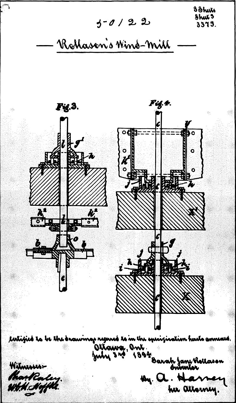
Figure 1 is a section of elevation. Figure 2 is a plan of the sails shield and outer frame, Figure 3 is a section showing the connection of the sails to a portion of spindle C and the arrangement of the two spindles C and 1 and the connection of the shield with spindle 1.
Figure 4 is a section of a portion of spindle C shewing spindle C passing clear through bearing of the shield down to its own bearing g on the bottom portions of the framework.
The sails (a) Figures 1 & 2 being made of wood or other suitable materials are preferably convex in form and are carried on curved arms (b) see Figures 1 & 2. The numbers required depend upon the size and strength of apparatus. The arms (b) are secured to iron bosses provided with lugs. The bosses being keyed or bolted at suitable distances on spindle (C) the arms (b) sails (a) and spindle (C) all rotate together when set in motion by the wind. On the concave side of each sail (a) are secured a number of ridges (e) Figures 1 and 2 so as to lie at a small angle with the horizontal, their upper ends pointing towards spindle (C). I have found the addition of such ridge to be very advantageous and to give increased power in the working of the wind wheel. The sails(a) do not extend right up to the spindle (C) but between it and the inner edge of each sail a considerable space(f) is left for the wind to pass through.
The spindle (C) carries the whole weight of the wind wheel with its sails and arms and passes clear through center of the bearing which carries the weight of the shield and continues down through the sleeve (g) and trough (j) to take wheel for driving. The sleeve (g) is keyed or bolted to spindle (C) and rotates on rollers (h) journalled in a plate (i) in trough (jj) which is bolted to bottom cross piece of (X) the lower portion of the external framing. The trough (j) is made deep enough to hold oil for rollers to work in. Around outer edge of sails (a) and inside the outer framing (X) is a round framework (k) Figures 1 and 2 supported and secured on four or more cross arms (k') bolted to bearings (y) and carried on rollers (h) in trough (j) see Figures 1 and 4 the trough (j) being screwed down to cross piece (X') Figures 1 and 4. The top of framework (k) is connected by four or more arms (k2) Figures 1 and 3 to spindle (l). The spindle (l) is carried upward through the top of apparatus (X) the vane (m) is secured to spindle (l). The frame work (k) spindle (l) and vane (m) revolve together. The two sleeves (z) and (g') carrying the weight of the spindle and vane in a similar manner to the sleeve (g) and the sleeve (Z) taking the side thrust. The spindle (l) passes clear through the troughs of (Z),(g') and cross pieces of (X) down below framework (k2) to form a pivot or top center for the wind wheel. The bearing (O) (see Figure 3) on the top of the wind wheel takes the end of spindle (l) and this forms the top bearing of the wind wheel. Fixed from bottom to top of framework (k) are boards or other suitable materials to cover about a third of the distance round to form the shield for shielding half of the apparatus see (k) Figures 1 and 2 to prevent the wind from striking the convex side of sails (a) thus stopping back resistance. The pointer vane (m) is set in a line with edge of shield (n) Figure 2 so as to bring the whole force of the wind upon the concave portion of sails. The small arrow Figure 3 denotes the direction the wind is supposed to be blowing thus shewing the object of shielding half of the apparatus. As the direction of the wind changes the vane regulates the position of the shield and causes it to travel round sails (a) until the pointer vane (m) faces the wind again. The weight of the shield and its spindle and vane is wholly taken by the bearings (y) and (g') so that the friction of the bearing (g) of the wind wheel is only that due to the weight of the wind wheel alone. It will be seen that by placing the framing (X) which supports the moving parts outside both shield and wind wheel I am enabled to obtain a lower bearing for the shield as described. This outer framing may conveniently take the form of a turret and be placed on the loftiest part of a building. The wheel on spindle (C) is geared or arranged for driving purposes.
Having now particularly described and ascertained the nature of my said invention and in what manner the same is to be performed, I declare that what I claim is,-
1. The general arrangements of wind-mill hereinbefore described comprising a wind wheel rotating round a vertical axis, a shield rotating round the same axis and automatically shifted by means of a vane and an external supporting framing, outside both the wind wheel and the shield which may conveniently take the form of an open turret substantially as described.
2. The arrangement for taking the weight of the shield with its spindle and vane, so that such weight dees not come upon the working spindle of the wind wheel but is independently supported, substantially as described.
3. The combined arrangement for taking the weights of the shield, wind wheel and other moving parts so as to obviate friction substantially as described.
4. The construction of wind wheel with its concave sails (a) ridges (e) and openings (f) substantially as described.
5. The arrangement of the upper bearing (O) of the wind wheel in combination with the spindle (l) or the shield or vane substantially as described.
Dated this fifth day of March, 1896.
PROVISIONAL SPECIFICATION.
"An improved windmill or wind motor"
I, Henry Hughes, of Wellington, in the Colony of New Zealand, Consulting Engineer, and Patent Agent, do hereby declare the nature of my invention for "An improved windmill or wind motor" to be as follows,-
The object of my invention is to provide a windmill or wind motor which is exceedingly simple in construction, having only four working parts, three of which move only as the wind changes. The windmill also is accurately balanced and works with a minimum of friction as it is fitted with ball bearings running in oil. The form of my wind motor is different from the ordinary construction of windmills which are now in use, it being a horizontal arrangement erected within a skeleton turret. From the top to the bottom of the centre or axis of the turret is provided a vertical shaft having concave sails attached which revolve on radius rollers immersed in oil. On the sails are fixed inclined ridges or planes which deflect the force exerted by the wind to their peripheries.
a water motor composed of a wheel having curved floats and a shield which may be arranged to cover or partly cover those floats moving in an opposite direction to that of the water in which the whole is submerged, the arrangement and construction of the bearings of axle of said wheel so that the weight of said wheel is carried by the upper bearing, and the lower bearing acts merely as a guide substantially as described with reference to the accompanying drawings.
New or Improved Mechanical and Electrical Appliance for Regulating and Controlling the Charging of Storage Batteries, the Supply of Water to Steam Generators, and for other purposes.
Date of Application, 3rd July, 1897
Complete Specification Left, 2nd Apr., 1898-Accepted, 2nd July, 1898
PROVISIONAL SPECIFICATION.
Improved Method of and Means for Exhibiting Advertisements.
We, WESTLEY HENRY FLETCHER (Architect), of 123, Abbey Road; GEORGE ROBERT ROLLASON (Engineer), of 16, Greenhill Road, Harlesden; and CHARLES ARTHUR ROLLASON (Engineer), of 6, Fairlight Avenue, Harlesden, all in the County of London, do hereby declare the nature of this invention to be as follows :-
The object of our invention is to produce an improved apparatus for exhibiting revolving advertisements in open spaces adjacent to railway lines or in any other suitable situation.
In carrying our invention into practical effect, we erect on the site where it is required to exhibit the advertisement or advertisements a vertical pillar or post which may be maintained in its vertical position by means of suitable stays if necessary.
Capable of revolving in a horizontal plane round this post or pillar on ball, roller, or other suitable bearings attached thereto, we place a number of collars or the like carrying radial arms at regular distances having attached thereto vertical sails. These arms and sails are concave in shape, all the sails facing in the same direction. These sails, which may each be of one piece of any suitable substance or material, or which may each be formed with a number of adjustable slats, carry the advertisements painted on or otherwise affixed thereto in any convenient manner and are caused to rotate in a horizontal plane round the said post or pillar by means of the wind.
If preferred the said arms carrying the vertical sails may be rigidly fixed to the said pillar or post which latter may then itself be capable of revolving in suitable bearings and be carried by a suitable framework.
Dated this 3rd day of July 1897.
The Largest Water Chute in the World. - This has lately been erected at the Crystal Palace under the superintendence of Mr. C. A. Rollason, one of the directors of Messrs. T. C. Williams and Sons, Ltd., of London-street Iron Works, Reading, the whole of the steel work in connection, being manufactured by that firm, in which about seventy tons of steel have been used. It is 72ft. high and has a clear run of 320ft., being much longer and higher than any chute in existence. It is supported on steel lattice girders, and while of ample strength, has a very light and pleasing appearance. We have no doubt that in the coming season it will form one of the great attractions to the popular place of amusement.
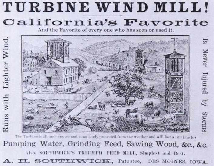
TURBINE WIND MILL!
California's Favorite
And the Favorite of every one who has seen or used it.
Runs with Lighter Wind.
Is Never Injured by Storms.
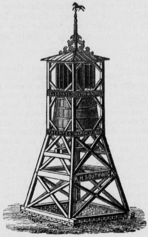
The Turbine is all under cover and completely protected from the weather and will last a lifetime for
Pumping Water, Grinding Feed, Sawing Wood, &c., &c.
Also, SOUTHWICK'S TRIUMPH FEED MILL, Simplest and Best.
A. H. SOUTHWICK, Patentee, DES MOINES, IOWA.
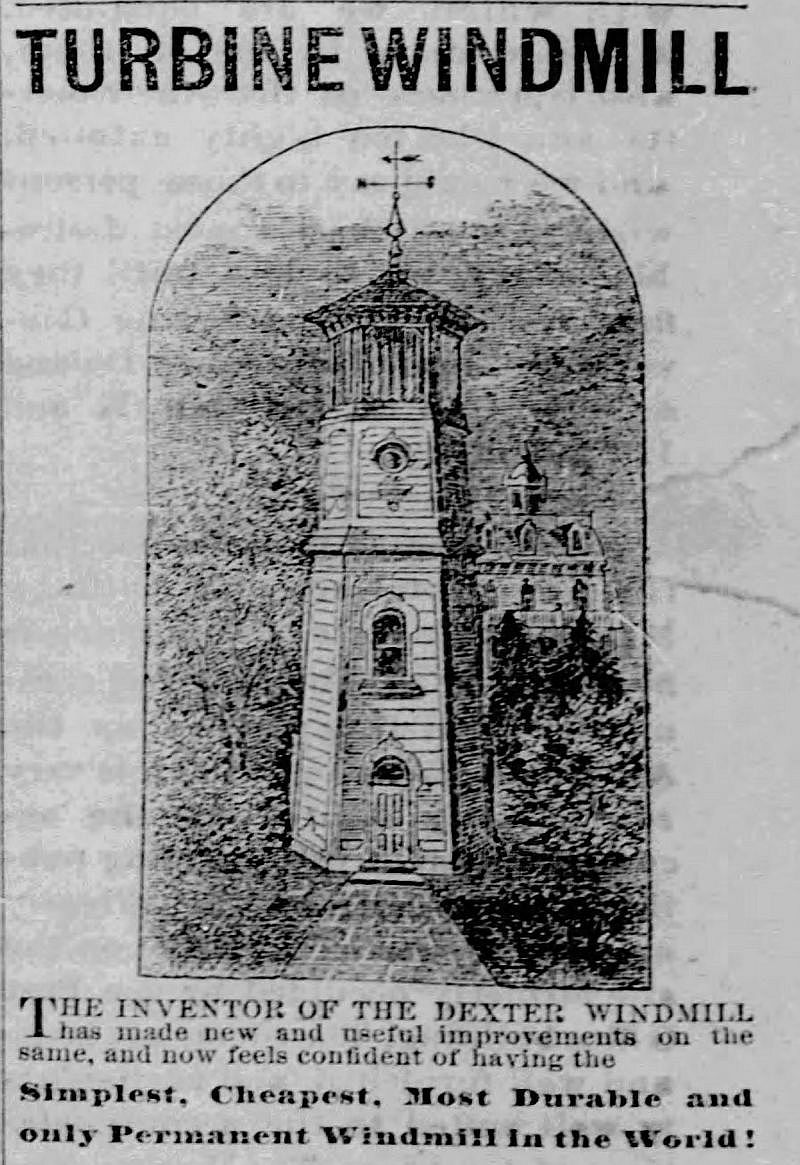
THE INVENTOR OF THE DEXTER WINDMILL
Has made new and useful improvements in Windmills, and now feels confident of having the SIMPLEST, CHEAPEST, MOST DURABLE, and ONLY PERMANENT WINDMILL IN THE WORLD. SIMPLEST, because it is less complicated; CHEAPEST, because it never needs repair, standing on a firm foundation; MOST DURABLE, because it is all under cover, and has less rigging to get out of order; ONLY PERMANENT, because the only Windmill in the world that has never been injured by storms. Hundreds of people, who have thought the Dexter perfect, will be glad to observe the SUPERIORITY OF THE TURBINE over all predecessors. Although much improved, the price of mills remain the same as formerly. Persons who study their own interest will investigate the TURBINE before purchasing any other.
Territory for sale outside of California, at reasonable rates and easy terms.
Mills Built to Order of the Best Material, and at the Shortest Notice.
For further information regarding Mills or Territory, address,
A. H. SOUTHWICK,
P. O. Box 1385, San Francisco; or
P. O. Box 25, Oakland, Cal.
These dry times it is well for us to post ourselves on the best means of obtaining a bountiful supply of water. The Turbine Windmill is the surest means for raising water from wells, as it never gets out of repair. People from all parts of the coast show their appreciation of the Turbine by sending in their orders liberally. We are now turning out the Turbine, in superior style and finish, as fast as they are ordered.
Kimball Co. are the only parties authorized to use the latest improvements ou the Turbine Windmill. Parties buying the Dexter with the improvements on, will be required to pay a royalty for the use of said improvements.
Parties purchasing the Turbine of Kimball Manufacturing Co., or their Agents, will be protected in their right to use them.
First come, first served, therefore send in your orders as soon as possible, and we guarantee satisfaction.
Address Kimball Manufacturing Co., office corner Fourth and Bryant Streets, San Francisco. (See advertisement in another column.)
THE OTHER SIDE.
TURBINE vs. DEXTER.
TO WHOM IT MAY CONCERN.
Whereas, the "Dexter Windmill Company" (composed of two individuals), have published a statement that the so-called Turbine Windmill is an infringement on the Dexter Windmill, and that said Dexter Windmill Company will prosecute any one who purchases the Turbine, I am called upon in the name of Truth and Justice to contradict their statement. The Turbine is no infringement on the patent held by Dexter Windmill Company. Read what Gov. H. H. Haight says on the subject: SAN FRANCISCO, April 22, 1875.
A. H. SOUTHWIOK, Esq .- Dear Sir: From an examination of the patent now held by the Dexter Windmill Company, and your patent dated March 16th, 1875, it seems clear to me that your right to manufacture and sell under your patent is unquestionable, without any license from the Dexter Windmill Company. If there were any room for question it would be disposed of by the fact, which I understood to be conceded, that the novelty of the invention patented to you first and transferred to the Dexter Company, consists in the combination with the Governor, and this is dispensed with in your patent of March 16th, 1875.
Respectfully yours, H. H. HAIGHT. Now, for two months or more I was Superintendent of the Dexter Windmill Company, and owned one-third of the stock of said company. I worked early and late in the interests of the company. I had to perform many duties not properly my own, while the secretary, who was receiving the same salary as myself, seemed entirely careless about his duties. Finally it was told me by one and another that there was to be an effort made to oust me out of my position. I did not believe the statement, but subsequent events have proved the truth of it. I was ruthlessly thrown from my position, and I asked in vain for an excuse for the act. I was answered with insults. My position and salary were given to the President, who did not devote one-fourth of the time and attention to the business that I had done. One officer who was incapacitated by a failing, and whose salary was the same as mine, was retained, and seemed to be the moving spirit in getting me out, and afterward made boast of it. "We went to work systematically to get Southwick out,and we succeeded." Then an assessment of one dollar per share was levied on the stock, as I now believe, for the express purpose of freezing me out, and the stock was bought in by the parties now owning it for the assessment and cost of advertising. I then became discouraged and thought of leaving the State. But I had been waiting a convenient time to apply a for patent on some very important improvements which I had made, and several of which the D. W. Co. were using. I then found that the improvements would insure me an opportunity to again engage in the Windmill business in California. I have secured the patent which covers the metal binding or shoe on the end of the shutters, and the pivot by which it is secured to the platforms, the overlapping shutter having its inner edge bent for the purpose of regulating the amount of wind admitted to the wheel. This takes the place of the governor in the other patent. Also, the lever above the wheel, pivoted in the center and connected by rods, cranks and gudgeons to the shutters in such a manner as to be easily worked by cord and pulleys to open and close the shutters. These improvements are owned only by the Kimball Manufacturing Company, who will furnish the mills and guarantee protection to the purchaser. Parties buying mille of the Dexter Windmill Company, manufactured after this date, are warned to be sure that said mills are free from said improvements, otherwise they will lay themselves liable to the law.
Any one wishing to see either or both of my patents can have an opportunity by applying to me anywhere, as I carry them always with me.
Respectfully,
A. H. SOUTHWICK,
Patentee Dexter and Turbine Windmills
Article: The Windmill Journal, Van Gelder - Plavia windmill Vol.18.No.2.Pages 1-8 (illus article)
| Last generated 30/06/2026 | Text and images © Mark Berry, 1997-2026 - |
